Telangana TSBIE TS Inter 2nd Year Physics Study Material 1st Lesson Waves Textbook Questions and Answers.
TS Inter 2nd Year Physics Study Material 1st Lesson Waves
Very Short Answer Type Questions
Question 1.
What does a wave represent?
Answer:
A wave is a disturbance which moves through a medium.
Waves transmit energy without trans-mitting matter. So waves will carry energy from one place to another place.
Question 2.
Distinguish between longitudinal and transverse waves.
Answer:
Longitudinal wave :
If the particles of the medium vibrate parallel to the direction of propagation of the wave then that wave is called “longitudinal wave”.
Ex : Sound waves in air.
These waves can be produced in solids, liquids and gases.
Transverse wave :
If the particles of the medium vibrate perpendicular to the direction of propagation of the wave, then that wave is called “transverse wave”.
Ex : Waves on a stretched string.
These waves can be produced only in solids.
Question 3.
What are the parameters used to describe a progressive harmonic wave?
Answer:
For a progressive wave (y) = a sin (ωt – kx)
The parameters in the above equation
1) a = Amplitude
2) ω = Angular velocity
3) υ = Frequency
4) T = Time period
5) λ = Wavelength
6) v = Velocity (v)
7) Φ = Phase
8) K = Propagation constant.
Question 4.
Obtain an expression for the wave velocity in terms of these parameters.
Answer:
Wave velocity :
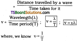
It is the distance travelled by the disturbance (energy) along the wave in one second. It is represented by V.
Wave Velocity ‘v’
Question 5.
Using dimensional analysis obtain an expression for the speed of transverse waves in a stretched string.
Answer:
Speed of transverse wave in a stretched string depends on tension (T) and linear density (µ).
Let v ∝ Ta µb ;
Dimension of velocity (v) = LT-1
Dimension of tension (T) = MLT-2 ;
Linear density (p) = ML-1
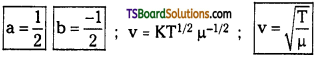
∴ v = K Ta µb
Where k is a dimensionless constant.
LT-1 = K (MLT-2)a (ML-1)b
= Ma La T-2a Mb L-b
M°L1T-1 = Ma + b La-b T-2a
Equating the powers of mass, length and time,
a + b = 0, a – b = 1 ⇒ – 2a = – 1

Question 6.
Using dimensional analysis obtain an ex-pression for the speed of sound waves in a medium.
Answer:
Speed of sound depends on wavelength and time period. v ∝ λa Tb
Dimensions of Velocity (v) = LT-1;
Dimensions of Wavelength (λ) = L;
Dimensions of Time period (T) = T;
L¹T-1 = LaTb
a = 1, b = – 1 ; v = λ¹ T-1
v = \(\frac{\lambda}{\mathrm{T}}\)
Question 7.
What is the principle of superposition of waves?
Answer:
When two waves are pulses overlap at a point the resultant displacement is the al¬gebraic sum of displacements due to each wave. Their resultant is also a wave.
y = (y1+ y2)
Question 8.
Under what conditions will a wave be reflected?
nswer:
Wave well be reflected if it falls on a rigid surface. Because at rigid surface the particles of medium does not vibrate.
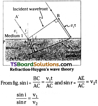
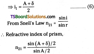
If a wave falls on the interface of two different elastic media, than a Part of two different elastic media, than a part of wave is reflected and a part of incident wave will be refracted. During refraction they obey Snell’s Law.
Question 9.
What is the phase difference between the incident and reflected waves when the wave is reflected by a rigid boundary?
Answer:
At rigid boundary phase difference between the incident and reflected wave = 180° (or) (π). Because at rigid boundary a node is formed.
Question 10.
What is a stationary (or) standing wave?
Answer:
When two progressive waves having same wavelength, amplitude and frequency travelling in the medium in opposite directions superposed stationary waves are formed.
Question 11.
What do you understand by the terms ‘node’ and ‘antinode’?
Answer:
Node :
The point where the displacement is minimum (zero) of a wave is called Node.
Antinode :
The point where the displacement is maximum of a wave is called Antinode.
Question 12.
What is the distance between a node and an antinode in a stationary wave?
Answer:
The distance between a node and an antinode = \(\frac{\lambda}{\mathrm{4}}\)
Question 13.
What do you understand by ‘natural frequency’ or ‘normal mode of vibration’?
Answer:
Natural frequency :
Vibrations produced by a body with elastic properties due to application of a constant force are known as natural frequency.
Ex : For a tuning fork natural frequency depends on elastic nature of the material, the mass distribution and the dimensions of the prongs of the fork.
Question 14.
What are harmonics?
Answer:
A harmonic is defined as a ‘tone’ of sound having a frequency which is an integral multiple of the fundamental frequency.
Question 15.
A string is stretched between two rigid supports. What frequencies of vibration are possible in such a string?
Answer:
The fundamental frequency of vibration and their harmonics are possible if a string is stretched between two rigid supports. If T is the natural frequency of vibration of the string, then possible their harmonics are 2f, 3f, 4f so on.
Question 16.
The air column in a long tube, closed at one end, is set in vibration. What harmonics are possible in the vibrating air column?
Answer:
If the fundamental frequency of the air column is denoted by f, then the frequencies at which the second, third, fourth and later modes occur are 3f, 5f, 7f …………… (2n – 1) f. A closed pipe will support only odd Har-monics.
Question 17.
If the air column in a tube, open at both ends, is set in vibration; what harmonics are possible?
Answer:
If the tube is open at both the ends is set in vibration, the frequencies of the harmonics present in an open pipe are integral multiples of fundamental frequency of the air column. Let f is fundamental frequency then possible harmonics are f, 2f, 3f…. etc.
Question 18.
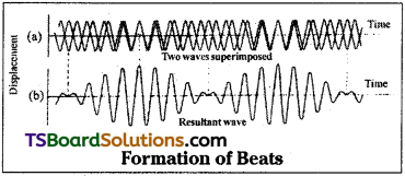
What are ‘beats’?
Answer:
Beats :
When two sounds of nearly equal frequency are superposed, they will create a waxing and warning intensity of sounds. This affect is called “beats”. Beats are produced due to interference of sound waves.
Beat frequency υbeat = υ1 – υ2
Question 19.
Write down an expression for beat frequency and explain the terms therein.
Answer:
Beat frequency (υbeat) = υ1 – υ2
Where υ1 and υ2 are the frequencies is of the two sound waves.
Question 20.
What is ‘Doppler effect’? Give an example.
Answer:
The apparent change in the frequency of source of sound due to relative motion between the source and observer is known as doppler’s effect.
Ex : The whistle of an approaching train appears to have high pitch. When the train is moving away pitch of its whistle decreases.
Question 21.
Write down an expression for the observed frequency when both source and observer are moving relative to each other in the same direction.
Answer:
When source and observer are moving in the same direction equation for observed
(or) apparent frequency υ = υ0 (\(\frac{v+v_{0}}{v+v_{s}}\))
Short Answer Questions
Question 1.
What are transverse waves? Give illustrative examples of such waves.
Answer:
Transverse Waves :
In these waves, the particles of the medium vibrate perpendicular to the direction of propagation of the wave.
These waves can propagate through solids and liquids.
Let a rope or string fixed at one end. At the other end continuous periodic up and down jerks are given by a external agency then transverse waves are produced.
Example:
Vibrations in strings, ripples on water surface and electromagnetic waves.
Question 2.
What are longitudinal waves? Give illustrative examples of such waves.
Answer:
Longitudinal waves :
In these waves particles of the medium vibrate parallel to the direction of propagation of the wave.
- These waves can propagate through solids and liquids and gases.
- A longitudinal wave travels in the form of compression and rarefaction.
- These waves are also known as “Compression waves”.
- In air sound waves are longitudinal waves.
Example :
Let a long pipe filled with air has a piston at one end. If the piston is pushed and pulled continuously then a series of compressions and rare fractions are produced. It represents a longitudinal wave.
Question 3.
Write an expression for a progressive harmonic wave and explain the various parameters used in the expression.
Answer:
Equation for progressive harmonic wave towards positive x-direction.
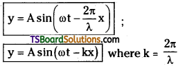
where y = displacement at any given time
A = amplitude of wave;
ω = angular velocity
along negative x-direction
y = Asin(ωt + kx)
General expression for wave motion y = A sin (ωt ± kx)
Question 4.
Explain the modes of vibration of a stretched string with examples.
Answer:
Equation of fundamental frequency :
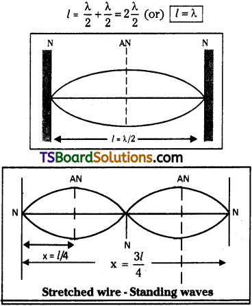
If the wire of length ‘l’ is stretched between points ‘A’ and ‘B’ with tension T vibrates as a single loop then the frequency of the vibrations is known as fundamental frequency and is denoted by ‘υ’.
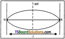
Than length of the wire (l) = \(\frac{\lambda}{\mathrm{2}}\) ⇒ λ = 2l.
But velocity of a wave (v) = υλ ……………. (1)
In case of stretched strings
v = \(\sqrt{\frac{T}{\mu}}\) …………. (2)
where v is the velocity of transverse vibrations in the string.
T = the tension.
µ = the linear density of the string,
υλ = \(\sqrt{\frac{T}{\mu}}\) (or) υ = \(\frac{1}{\lambda}\) \(\sqrt{\frac{T}{\mu}}\) From (1)
When one loop is formed
∴ υ = \(\frac{1}{2l}\)\(\sqrt{\frac{T}{\mu}}\) (∵ λ = 2l)
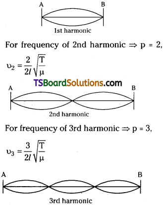
If the wire vibrates for p loops, then the frequency υp = \(\frac{p}{2l}\)\(\sqrt{\frac{T}{\mu}}\)
Laws of Transverse vibrations in a stretched string:
I. First Law (or) Law of length :
The fundamental frequency of a vibrating string is inversely proportional to the length of the string, when the tension (T) in the string and linear density p are constant.
υ ∝ \(\frac{1}{l}\) ⇒ υl = constant
when T and ‘µ’ are constant.
II. Second law (or) Law of Tension :
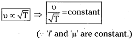
The fundamental frequency of a vibrating string is directly proportional to the square root of stretching force T (Tension), when the length of the string and linear density ‘µ’ are constant.
υ ∝ √T ⇒ \(\frac{υ}{\sqrt{T}}\) = constant
when T and ‘µ’ are constant.
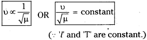
III. Third law (or) Law of linear density (or) Law of mass :
The fundamental frequency of a vibrating string is inversely proportional to the square root of the linear density (µ) when the length (l) and tension (T) in the string are constant.
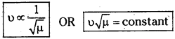
when ‘l’ and ‘T’ are constant
Examples :
An exciting tuning fork, the plucked wire of a stringed instrument, a bell struck with a hammer, a vibrating air column in a trumpet are some of examples of stretched string.
Question 5.
Explain the modes of vibration of an air column in an open pipe.
Answer:
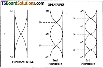
Harmonics in open pipe: In the fundamental mode of vibration, an antinode is formed at each end with a node formed between them.
If ‘l’ is the vibrating length and λ1 is the corresponding wavelength.
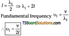
l = \(\frac{\lambda_{1}}{2}\),
The frequency of fundamental mode
(or) 1st harmonic υ1 = \(\frac{v}{\lambda_{1}}\) ∴ υ1 = \(\frac{v}{2l}\)
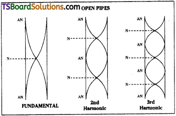
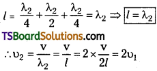
Second Harmonic (or) first overtone :
It will have three antinodes and two nodes.
If λ2 is the corresponding wavelength
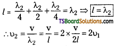
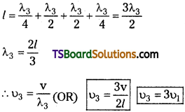
Third harmonic (or) Second overtone :
It will have four antinodes and three nodes. If λ3 is the corresponding wavelength,
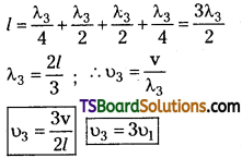
In open pipe harmonics are in the ratio of 1 : 2 : 3 …………..
Question 6.
What do you understand by ‘resonance’? How would you use resonance to deter-mine the velocity of sound in air?
Answer:
Resonance :
If the natural frequency of the body coincides with frequency periodic force impressed on it, then the body is said to be at resonance.
At resonance, the body vibrates with increasing amplitude.
Determination of velocity of sound using Resonance :
Consider a closed tube where air column length can be changed.
For the First resonance :
Length of air column is equal to = l1 + e = \(\frac{\lambda}{4}\) → (1)
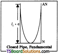
where e is endcorrection
For the Second resonance :
Length of air column is equal to = l2 + e = \(\frac{3\lambda}{4}\) → (2)
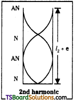
Length of the second resonating air column is approximately equal to three times the length of first resonating air column.
(2) – (1)
l2 – l1 = \(\frac{3\lambda}{4}-\frac{\lambda}{4}=\frac{\lambda}{2}\)
⇒ λ = 2(l2 – l1)
Velocity of sound in air
v = υλ
v = 2υ(l2 – l1)
where υ = the frequency of tuning fork, l1, l2 = first and second resonating lengths.
Quetion 7.
What are standing waves? Explain how standing waves may be formed in a stretched string.
Answer:
Stationary waves (or) standing waves :
When a progressive wave and reflected wave superpose with suitable phase a steady wave pattern is set up on the string or in the medium.
A standing wave is represented by y (x, t) = 2a sin kx cos ωt.
Formation of standing waves in stretched strings :
Let a wire of length V and mass’m’ is fixed between two fixed supports with some tension T.
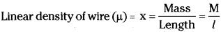
Let the wire is plucked at the mid point then it will vibrate with maximum amplitude. So antinode (A.N) is formed at centre of wire. At the fixed ends molecules of the wire are not free to vibrate. So nodes will be formed at fixed ends as shown in figure.
Now length of wire l = \(\frac{\lambda}{2}\).
If two loops are formed,
Quetion 8.
Describe a procedure for measuring the velocity of sound in a stretched string.
Answer:
Let a wire of length ‘l’ and mass M is fixed between two rigid supports.
Practical method :
To measure velocity of sound in stretched strings we will adjust length of wire until stationary waves are formed in the given string by means of the tuning fork in the sonometer expt.. When
length of string (l) is equals to \(\frac{\lambda}{2}\)
l = \(\frac{\lambda}{2}\)
But υ = nλ or υ = n × 2l
Question 9.
Explain, using suitable diagrams, the formation of standing waves in a closed pipe. How may of this can be used to determine the frequency of a source of sound?
Answer:
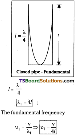
Stationary waves formed in a closed pipe :
If one end is closed and the other end is open, then it is called a ‘Closed pipe’.
Let a longitudinal wave be sent through a closed pipe. It gets reflected at the closed end. These incident and reflected waves which are of same frequency, travelling in opposite directions gets superposed along the length of the pipe. As a result of it, longitudinal stationary waves are formed. In a closed pipe
υn = \(\frac{(2n+1)υ}{4l}\)
For 1st harmonic, when n = 0, υ1 = \(\frac{υ}{4l}\)
For 2nd harmonic, when n = 1, υ2 = 3\(\frac{υ}{4l}\)
For 3rd harmonic, when n = 2, υ2 = 5\(\frac{υ}{4l}\)
From resonating air column expt. the frequency of sound can be found by using the formula
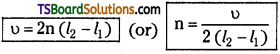
Where l1 ansd l2 1st and 2nd resonating lengths and n is the frequency of the tuning fork.
Question 10.
What are ‘beats’? When do they occur? Explain their use, if any.
Answer:
Beats :
When two sounds of nearly equal frequency are superposed, they will create a waxing and warning intensity of sounds. This effect is called “beats”.
Beats are produced due to interference of sound waves.
Beat frequency υbeat = υ1 – υ2
Uses of Beats:
- To know the frequency of an unknown tuning fork.
- Harmful gases in a mine can be detected by using beats.
Question 11.
What is ‘Doppler effect’? Give illustrative examples.
Answer:
Doppler effect :
The apparent change in frequency heard by the observer due to the relative motion between source and the observer is called “Doppler’s effect”.
Examples of Doppler effect:
- The frequency of sound increases as the source moves closer to the observer. Ex: Pitch of the whistle of an approaching train appears to be increased and that of a train going away decreases.
- In astronomy, the Doppler effect was originally studied in the visible part of the electromagnetic spectrum.
Because of the inverse relationship between frequency and wavelength, we can describe the Doppler shift in terms of wavelengths. Radiation is redshifted when its wavelength increases. It indicates that the stars are moving away and universe is expanding.
Long Answer Questions
Question 1.
Explain the formation of stationary waves in stretched strings and hence deduce the equations for first, second and third harmonics and also deduce the laws of transverse waves is stretched strings. [TS Mar. 19; AP & TS May 18, 16]
Answer:
Stationary wave :
When two progressive waves of same wavelength, amplitude and frequency travelling in opposite directions and superimpose over each other stationary waves (or) standing waves are formed.
Formation of stationary wave in a stretched string:
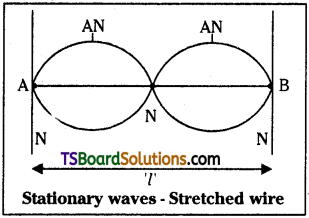
- Let us consider a string of length ‘l’ stretched at the two fixed ends ‘A’ and ‘B’.
- Now pluck the string perpendicular to its length.
- The transverse wave travel along the length of the string and get reflected at fixed ends.
- Due to superimposition of these reflected waves, stationary waves are formed in the string.
Equation of Stationary Wave :
Let two transverse progressive waves having same amplitude ‘A’, wavelength λ and frequency ‘n’; travelling in opposite direction along a stretched string be given by
y1 = A sin (kx – ωt) and y2 = A sin (kx + ωt)
where ω = 2πn and k = \(\frac{2 \pi}{\lambda}\)
Applying the principle of superposition of waves, the resultant wave is given by
y = y1 + y2
y = A sin (kx – ωt) + A sin (kx + ωt)
y = 2A sin kx cos ωt
Amplitude of resultant wave (2A sin kx) is no more constant. It depends on the
value of kx. When x = 0, \(\frac{\lambda}{2},\frac{2\lambda}{2}.\frac{3\lambda}{2}\), …………… etc.
The amplitude becomes zero.
These positions of zero amplitude are
known as “Nodes”, when x = \(\frac{\lambda}{4},\frac{3\lambda}{4}.\frac{5\lambda}{4}\), ……………. etc. The amplitude becomes 2A (Maximum).
These positions of maximum amplitude are known as “Antinodes”.
Equation of fundamental frequency :
If the wire of length ‘l’ is stretched between points ‘A’ and ‘B’ with tension T vibrates as a single loop then the frequency of the vibrations is known as fundamental frequency and is denoted by ‘υ’.
l = \(\frac{\lambda}{2}\)
But velocity of a wave v = υλ – (1)
In case of stretched strings v = \(\sqrt{\frac{T}{\mu}}\) – (2)
From (1) and (2)
υ = \(\frac{1}{\lambda}\sqrt{\frac{T}{\mu}}\)
∴ υ = \(\frac{1}{2l}\sqrt{\frac{T}{\mu}}\) (∵ λ= 2l)
If the wire vibrates for ‘p’ loops _P If
The frequency = υp = \(\frac{p{2l}\sqrt{\frac{T}{\mu}}\)
Formation of harmonics in stretched strings :
From above equation if the wire vibrates with one loop then p =1
Frequency of 1st harmonic υ1 = \(\frac{1}{2l}\sqrt{\frac{T}{\mu}}\)
Laws of Transverse vibrations in a stretched string :
I. First Law (or) Law of length :
The fundamental frequency of a vibrating string is inversely proportional to the length of the string, when the tension (T) and its
linear density µ are constant.
υ ∝ \(\frac{1}{l}\) ⇒ υl = constant ⇒ υ1l1 = υ2l2 (∵ T, µ are constant)
II. Second law (or) Law of Tension :
The fundamental frequency of a vibrating string is directly proportional to the square root of stretching force T (Tension), when the length of the string l and linear density ‘µ’ are constant.
III. Third law (or) Law of linear density :
The fundamental frequency of a vibrating string is inversely proportional to the square root of the linear density (m) when the length (l) and tension (T) in the string are constant.
Question 2.
Explain the formation of stationary waves in an air column enclosed in open pipe. Derive the equation for the frequencies of harmonics produced. [(TS May 17, Mar. 16; AP Mar. 18, 17, 16, May 17, 14)]
Answer:
Formation of stationary wave in open pipe :
An open pipe is a cylindrical tube having air inside with both ends open.
Let a longitudinal wave pass through the organ pipe. It gets reflected at the end of the pipe. These incident and reflected waves which are of same frequency, travelling in opposite directions, get superposed along the length of the pipe.
As a result of it, longitudinal stationary waves are formed.
At the open end, the particles of the medium are free to vibrate and the incident and reflected waves will be in phase, so particles have maximum displacement, forming antinode. Thus the air column in- side a open pipe is set into vibration due to stationary waves formed in it with anti- node at each open end.
Harmonics in open pipe :
Fundamental :
In the fundamental mode of vibration, an antinode is formed at each end and a node is formed between them. The note produced is called first harmonic.
If ‘l’ is the vibrating length and λ1 is the corresponding wavelength.
Second Harmonic (or) first overtone :
2nd harmonic consists of three antinodes and two nodes.
If λ2 is the corresponding wavelength
Third harmonic or Second overtone :
3rd harmonic consists of four antinodes and three nodes. If λ3 is the corresponding wavelength,
The ratio of harmonics in open pipes υ1 : υ2 : υ2 : = 1 : 2 : 3 …………
Question 3.
How are stationary waves formed in closed pipes? Explain the various modes of vibrations and obtain relations for their frequencies. [T.S. Mar. ’19, ’15, May, June ’15; AP Mar. June ’15, May ’17, ’16]
Answer:
A closed pipe is a cylindrical tube having air inside, one end closed and the other is open.
Let a longitudinal wave be sent through a closed pipe. It gets reflected at the closed end of the pipe. These incident and reflected waves, which are of same frequency, trav-elling in opposite directions gets superposed as a result longitudinal stationary waves are formed.
At the closed end reflection is on a rigid surface a node is formed at closed end, at the open end antinode is formed.
I. Harmonics in a closed pipe :
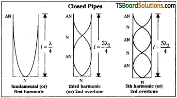
Fundamental mode (or) First Harmonic :
In this one node and one antinode is formed. If ‘l’ is the vibrating length and λ1 is the corresponding wavelength.
II. First overtone or Third Harmonic :
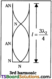
1st overtone consists of two nodes and two antinodes. If ‘l’ is the vibrating length and λ3 is the corresponding wavelength,
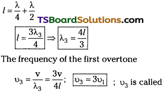
as third Harmonic or first overtone.
III. Fifth Harmonic or Second overtone :
2nd overtone consists of three nodes and three antinodes.
If ‘l’ is the vibrating length, λ5 is the corresponding wavelength,
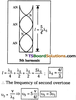
υ5 is called fifth Harmonic.
The ratio of harmonics in closed pipe is υ1 : υ3 : υ5 : = 1 : 3 : 5 : ………….
From the above, in closed pipe only odd Harmonics are formed.
Question 4.
What are beats? Obtain an expression for the beat frequency. Where and how are beats made use of?
Answer:
When two sounds of nearly (or) slightly equal frequency are superposed they will create a waxing and warning intensity of sounds. This effect is called “beats”.
Beats are produced due to interference of sound waves.
Beat frequency ubeat υbeat = υ1 ~ υ2
Expression for beat frequency:
Let us consider two sound waves y1 and y2 of nearly equal frequency ‘υ1‘ and ‘υ2‘ each of amplitude a’ superpose each other then the resultant wave is given by
y = y1 + y2 = a sin ω1t + a sin ω2t.
where ω1 = 2πυ1 and ω2 = 2πυ2;
∴ y = a sin 2πυ1t + a sin 2πυ2t
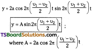
The frequency of the resultant wave is \(\frac{υ_1+υ_2}{2}\)
The frequency of the amplitude is \(\frac{υ_1-υ_2}{2}\)
The intensity of the sound will be maximum when 2a cos 2π(\(\frac{υ_1-υ_2}{2}\)) is maximum.
Where k = 0, 1, 2, …………. maximum sound will be heard at interval
0, \(\frac{1}{υ_1-υ_2},\frac{2}{υ_1-υ_2},\frac{3}{υ_1-υ_2}\)
The time interval between two consecutive maxima = \(\frac{1}{υ_1-υ_2}\)
or, Beat frequency = υ1 – υ2
The intensity of sound will be minimum when cos 2π(\(\frac{υ_1-υ_2}{2}\))t is minimum i.e., zero.
The time interval between two consecutive minima = \(\frac{1}{υ_1-υ_2}\)
The number of minima heard per second = υ1 ~ υ2
Importance of Beats: Beats can be used
- in tuning musical instruments.
- to detect dangerous gases in mines.
- to produce special effects in cinematography.
- to determine unknown frequency of a tuning fork.
- in heterodyne receivers range.
Question 5.
What is Doppler effect? Obtain an expression for the apparent frequency of sound heard when the source is in motion with respect to an observer at rest. [(AP Mar. 16, 14; TS Mar. 18, 17]
Answer:
Doppler effect :
The apparent change in the frequency heard by the observer due to relative motion between the observer and the source of sound is called “Doppler effect”.
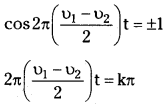
Expression for apparent frequency when source is in motion and observer at rest:
Let ‘s’ be a source of sound moving with a velocity vs away from a stationary observer. Let the source produces a sound of frequency υ0 and its time period is T0.
At time t = 0 the source produces a crest.
Let the distance between source and observer is ‘L’ and velocity of sound is ‘v’.
Then time taken by observer to detect crest = t1 = \(\frac{L}{v}\) ……… (1)
The second crest is produced after a time interval T0.
Distance travelled by source during this time = vsT0. So total distance from observer = L + vsT0
Time taken to detect 2nd crest
Let the source produced (n + 1)th crest at time nT0.
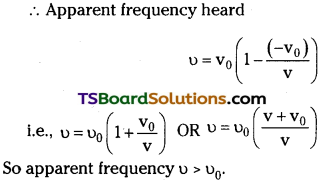
Now time taken to detect that crest =
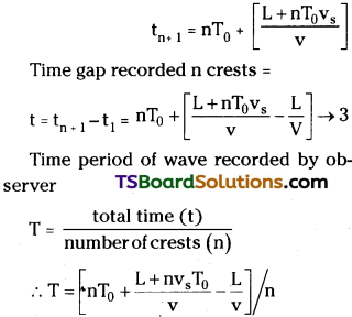
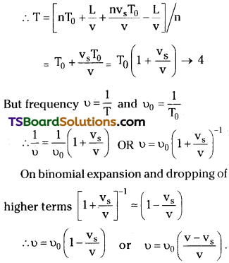
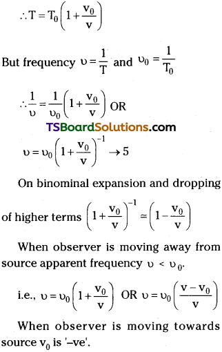
So apparent frequency υ < υ0.
If source is moving towards observer, then vs is -ve (as per sign convension).
∴ apparent frequency υ = υ0 [1 – \(\frac{(-v_s)}{v}\)]
= υ0 [1 + \(\frac{v_s}{v}\)]
When source is approaching the observer frequency heard υ = υ0(\(\frac{v+v_s}{v}\)) OR
υ = υ0 [1 + \(\frac{v_s}{v}\)]. In this case apparent frequency heard υ > υ0.
Question 6.
What is Doppler shift? Obtain an expression for the apparent frequency of sound heard when the observer is in motion with respect to a source at rest. [AP June ’15]
Answer:
Doppler shift :
The difference between apparent frequency heard by observer and actual frequency produced by the source is called as “Doppler’s shift”.
Derivation of apparent frequency when source at rest and observer in motion :
Let s’ is a source at rest produces a sound of constant frequency ‘υ0‘ Let Time Period of wave is ‘T0‘. Let an observer is moving away from source with a velocity ‘v0‘.
Carries a device that can count the num-ber of crests / compressions produced by source.
At time t = 0 source produces a crest. Let the distance between source and observer is L’ and velocity of sound is ‘v’.
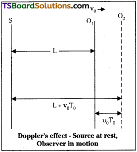
Now time taken by the observer to detect the crest t1 = \(\frac{L}{v}\) → 1
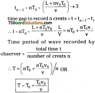
2nd crest is produced after a time period T0.
During this time observer moves a distance v0T0
time taken by observer to detect t2 = T0 + (\(\frac{L+T_{0}v_{0}}{v}\)) → 2
Let source produces (n + 1) th crest after a time nT0
Time taken to detect this crest
Solved Problems
Question 1.
A stretched wire of length 0.6 m is observed to vibrate with a frequency of 30 Hz in the fundamental mode. If the string has a linear mass of 0.05 kg/m find (a) the velocity of propagation of transverse waves in the string (b) the tension in the string. [AP May 18; TS May 16]
Answer:
Vibrating length (l) = 0.6 m
For fundamental mode l = \(\frac{\lambda}{2}\)
⇒ λ = 2l = 2 × 0.6 ⇒ λ = 1.2 m
Fundamental frequency n = 30 Hz
a) Velocity of transverse wave v = nλ ;
v = 30 × 1.2 ⇒ v = 36 ms-1
b) Linear density of the string
µ = 0.05 kg m-1
But, v = \(\sqrt{\frac{T}{\mu}}\) (T is the tension)
T = v²µ = 36 × 36 × 0.05 = 64.8 N.
Question 2.
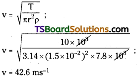
A steel cable of diameter 3 cm is kept under a tension of 10 kN. The density of steel is 7.8g/cm³. With what speed would transverse waves propagate along the cable?
Answer:
The density of steel is
ρ = 7.8 gm cm-3 ⇒ 7.8 × 10³ kgm-3
Diameter of cable D = 3 cm
⇒ r = 1.5 × 10⁻² m
Tension (T) = 10 × 10³ N.
Question 3.
Two progressive transverse waves given by y1 = 0.07 sin π (12x – 500t) and y2 = 0.07 sin π (12x + 500t) travelling along a stretched string form nodes and antinodes. What is the displacement at the (a) nodes (b) antinodes? (c) What is the wavelength of the standing wave?
Answer:
Equation of progressive wave is
y1 = 0.07 sin (12πx – 500 πt) ;
y2 = 0.07 sin (12πx + 500 πt)
a) Displacement at node = 0
b) Displacement at Antinode = 2A = 2 × 0.07 = 0.14 m.
c) Propagation constant k = 12π
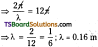
Question 4.
A string has a length of 0.4 m and a mass of 0.16 g. If the tension in the string is 70 N, what are the three lowest frequencies it produces when plucked?
Answer:
Length of string (l) = 0.4 m
Mass of the string (m) = 0.16 × 10⁻³kg ;
Linear density (µ) = \(\frac{0.16}{0.4}\) = 4 × 10⁻⁴ kg m-1
Tension (T) = 70 N.
Fundamental frequency υ1 = \(\frac{1}{2l}\sqrt{\frac{T}{\mu}}\) ;
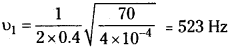
Next frequency is υ2 = 2υ1
= 2 × 523 = 1046 Hz
Next frequency is υ3 = 3υ1
= 3 × 523 = 1569 Hz
Question 5.
A metal bar when clamped at its centre, resonates in its fundamental frequency with longitudinal waves of frequency 4 kHz. If the clamp is moved to one end, what will be its fundamental resonance frequency?
Answer:
Fundamental frequency (υ) = 4 × 10³ Hz
a) If metal bar is clamped at its centre
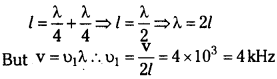
b) If metal is clamped at one end
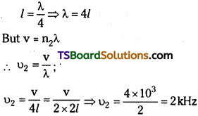
Question 6.
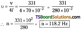
A closed organ pipe 70 cm long is sounded. If the velocity of sound is 331 m/s, what is the fundamental frequency of vibration of the air column? [TS Mar. ’19; AP Mar. 18, I 7, May 1 7, 14]
Answer:
Length of closed organ pipe l = 70 cm
Velocity of sound (v) = 331 ms-1
Fundamental frequency of closed pipe
Question 7.
A vertical tube is made to stand in water so that the water level can be adjusted. Sound waves of frequency 320 Hz are sent into the top the tube. If standing waves are produced at two successive water lev-els of 20 cm and 73 cm, what is the speed of sound waves in the air in the tube?
Answer:
Frequency of sound wave (n) = 320 Hz
1st resonating length l1 = 20 cm
2nd resonating length l2 = 73 m
Speed of sound wave (v) = 2n (l2 – l1)
= 2 × 320 (73 – 20)
∴ v = 640 × 53 × 10-2
= 33920 cm s-1 = 339 ms-1
Question 8.
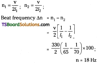
Two organ pipes of lengths 65 cm and 70 cm respectively, are sounded simultaneously. How many beats per second will be produced between the fundamental frequencies of the two pipes? (Velocity of sound = 330 m/s).
Answer:
First open organ pipe of length (l1) = 65 cm
Second open organ pipe of length (l2) = 70 cm
Question 9.
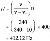
A train sounds its whistle as it approaches and crosses a level-crossing. An observer at the crossing measures a frequency of 219 Hz as the train approaches and a frequency of 184 Hz as it leaves. If the speed of sound is taken to be 340 m/s, in the speed of the train and the frequency of its whistle.
Answer:
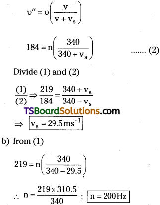
a) Speed of sound (v) = 340 ms-1 ;
Apparent frequency heard by observer when train approaches υ’ = 219 Hz
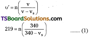
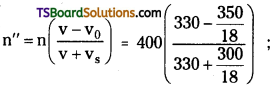
When train leaves the observer ap-parent frequency n” = 184 Hz
Question 10.
Two trucks heading in opposite directions with speeds of 60 kmph and 70 kmph respectively, approach each other. The ckiver of the first truck sounds his horn of frequency 400 Hz. What frequency does the driver of the second truck hear? (Velocity of sound = 330 m/s). After the two trucks have passed each other, what frequency does of the second truck hear?
Answer:
Speed of first truck = 60 × \(\frac{5}{18}\) = vs
Speed of second truck = 70 × \(\frac{5}{18}\) = v0
Frequency of first truck n = 400 Hz ;
Velocity of sound = 330 ms-1
a) When they approach each other, frequency heard by second truck driver is
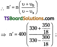
∴ Apparent frequency (n’) = 600 Hz b)
b) When they move away from each other, the frequency heard by second truck driver
∴ Apparent frequency υ” = 270 Hz
Question 11.
A rocket is moving at a speed of 200 ms-1 towards a stationary target. While moving, it emits a wave of frequency 1000 Hz. Calculate the frequency of the sound as detected by the target. (Velocity of sound in air is 330 ms-1) [AP Mar. ’16]
Answer:
Velocity of source (Rocket) (Vs) = 200 m/s
Velocity of sound (V) = 330 m/s.
Frequency of sound emitted (υ0) = 1000 Hz
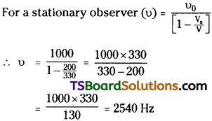
Frequency of sound heard by observer υ = 2540 Hz.
Question 12.
A open organ pipe 85 cm long is sounded. If the velocity of sound is 340 m/s, what is the fundamental frequency of vibration of the air column? [TS Mar. ’16]
Answer:
Length of pipe (l) = 85 cm,
Velocity of sound (V) = 340 m/s.
Fundamental frequency of open pipe = n
= \(\frac{V}{2l}\)
n = \(\frac{340 \times 100}{2 \times 85}\) = 200Hz
∴ Fundamental frequency (n) = 200 Hz.
Question 13.
A pipe 30 cm long is open at both ends. Find the fundamental frequency. Velocity of sound in air is 330 ms-1.
Answer:
Length of open pipe (l) = 30 cm;
Velocity of sound (V) = 330 ms-1
At fundamental frequency λ = 2l.
⇒ λ = 30 × 2 = 60 cm = 0.6 m
Fundamental frequency
v = \(\frac{V}{\lambda}=\frac{330}{0.6}\) = 550 Hz.
Question 14.
If the fundamental frequency in a closed pipe is 300Hz, find the value of third har¬monic in it. [TS June ’15]
Answer:
Fundamental frequencies (v1) = 300Hz
Frequencies of 3rd Harmonic (v3) = 3v1
= 300 × 3 = 900Hz
Note: In closed pipes, the harmonics are in the ratio 1:3:5 even harmonic does not exist.
Intext Question and Answer
Question 1.
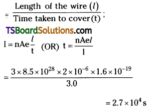
A string of mass 2.50 kg is under a tension of 200 N. Then length of the stretched string is 20.0 m. If the transverse jerk is caused at one end of the string, how long does the disturbance take to reach the other end?
Answer:
Mass of the string, (M) = 2.5 kg
Tension in the string, (T) = 200 N
Length of the string (l) = 20 m
Linear density (µ) = mass per unit length = \(\frac{M}{l}=\frac{2.5}{20}\) = 0.125 kgm-1
Velocity of transverse wave in the string is
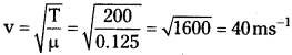
∴ Time taken by the disturbance to reach the other end, t = \(\frac{l}{v}=\frac{20}{40}\) = 0.5 s.
Question 2.
A stone dropped from the top of a tower of height 300 m splashes into the a pond of water near the base of the tower. When is the splash heard at the top given that the speed of sound in air is 340 ms-1? (g = 9.8 ms-2)
Answer:
Height of the tower (n) = 300 m
Initial velocity (u) = 0
Acceleration due to gravity, g = 9.8 m/s²
Speed of sound = 340 ms-1
The time (t1) taken by the stone to strike the water in the pond can be calculated using
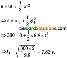
Time taken (t2) by the sound to reach the top of the tower, t2 = \(\frac{h}{u}=\frac{300}{340}\) = 0.88 s
∴ Total time after the splash is heard,
t = t1 + t2 = 7.82 + 0.88 = 8.7 s.
Question 3.
A steel wire has a length of 12 in and a mass of 2.1 kg. What should be the tension in the wire so that speed of a transverse wave on the wire equals the speed of sound in dry air at 20°C = 343 ms-1.
Answer:
Length of the wire (l) = 12 m ;
Mass of the wire (M) = 2.1 kg
Linear density (µ) = mass per unit length
= \(\frac{M}{l}=\frac{2.1kg}{12m}\) = 0.175 kgm-1
We know that velocity of a transverse wave in a stretched string is given by
v = \(\sqrt{\frac{T}{\mu}}\) ⇒ v²µ = (343)² × 0.175
= 20588 × 575 N ≅ 2.06 × 10⁴ N.
Question 4.
A bat emits ultrasonic sound of frequency 1000 kHz in air. If the sound meets a water surface, what is the wavelength of (a) the reflected sound, (b) the transmitted sound? Speed of sound in air is 340 ms-1 and in water 1486 ms-1.
Answer
a) Frequency of ultrasonic sound,
n = 1000 kHz = 106 Hz
Speed of sound (va) = 340 ms-1
The wavelength (λr) of the reflected sound is given by
λr = \(\frac{υ_{a}}{n}=\frac{340}{10^{6}}\) = 3.4 × 10⁻⁴ m
b) Frequency of the ultrasonic sound,
n = 1000 kHz = 106 Hz
Speed of sound in water, υw = 1486 ms-1.
The wavelength (λr) of the reflected sound is given by
λr = \(\frac{υ_{w}}{n}=\frac{1486}{10^{6}}\) = 1.49 × 10⁻³ m
Question 5.
A hospital uses an ultrasonic scanner to locate tumours in a tissue. What is the wavelength of sound is 1.7 kms-1? The operating frequency of the scanner is 4.2 MHz.
Answer:
Speed of sound in the tissue,
v = 1.7 km s-1 = 1.7 × 10³ ms-1
Operating frequency of the scanner,
n = 4.2 MHz = 4.2 × 10⁶ Hz
The wavelength of sound in the tissue is
λ = \(\frac{\mathrm{v}}{\mathrm{n}}=\frac{1.7 \times 10^3}{4.2 \times 10^6}\) = 4.1 × 10⁻⁴ m
Question 6.
A wire stretched between two rigid supports vibrates in its fundamental mode with a frequency of 45 Hz. The mass of the wire is 3.5 × 10⁻² kg and its linear mass density is 4.0 × 10⁻² kg m-1. What is (a) the speed of a transverse wave on the string, and (b) the tension in the string?
Answer:
a) Mass of the wire, M = 3.5 × 10⁻² kg m-1
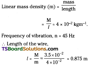
The wavelength (λ) of the stationary wave is related to the length of the wire by the relation
λ = \(\frac{2l}{n}\)
where n → no. of nodes in the wire
For fundamental node, n = 1
λ = 2l = 2 × 0.875 = 1650 m.
The speed of the transverse wave is given by
v = nλ = 4.5 × 1.75
= 78.75 ms-1
b) The tension produced in the string is given by the formula
T = v²m = (78.75)² × 4 × 10-2
= 248.06 N.
Question 7.
A steel rod 100 cm long is clamped at its middle. The fundamental frequency of longitudinal vibrations of the rod is given to be 2.53 kHz. What is the speed of sound in steel?
Answer:
Length of the steel rod, l = 100 cm = 1 m.
Fundamental frequency of vibration,
n = 2.53 kHz = 2.53 × 10³ Hz

When the rod is plucked at its middle, an antinode is formed at its centre and nodes (N) are formed at its two ends as shown in the given figure.
The distance between two successive nodes is \(\frac{\lambda}{2}\).
∴ l = \(\frac{\lambda}{2}\)
⇒ λ = 2l = 2 × l = 2m
The speed of sound in steel is given by the relation:
v = nλ= 2.53 × 10³ × 2
= 5.06 × 10³ ms-1
= 5.06 kms-1
Question 8.
A train, standing at the outer signal of a railway station blows a whistle of freq-uency 400 Hz in still air.
i) What is the frequency of the whistle for a platform observer when the train
a) approaches the platform with a speed of 10 ms-1,
b) recedes from the platform with a speed of 10 ms-1?
ii) What is the speed of sound in each case? The speed of sound in still air can be taken as 340 ms-1.
Answer:
i) a) Frequency of the whistle (n) = 400 Hz
Speed of the train (vt) = 10 ms-1
Speed of sound (v) = 340 ms-1
The apparent frequency (n’) of the whistle as the train approaches the platform is given by the relation
b) The apparent frequency (n’) of the whistle as the train recedes from the platform is given by the relation :
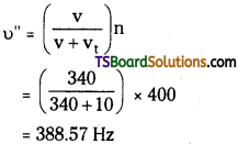
ii) The apparent change in frequency of sound is caused by the relative motions of the source and the observer. These relative motions produce no effect on the speed of sound. Therefore, the speed of sound in air in both the cases remains the same i.e., 340 ms-1.