Telangana TSBIE TS Inter 2nd Year Physics Study Material 9th Lesson Electromagnetic Induction Textbook Questions and Answers.
TS Inter 2nd Year Physics Study Material 9th Lesson Electromagnetic Induction
Very Short Answer Type Questions
Question 1.
What did the experiments of Faraday and Henry show?
Answer:
- Faraday and Henry experiments showed that the relative motion between the magnet and a coil is responsible for generation of electric current in the coil.
- The relative motion is not an absolute requirement to induce the current in a coil. If the current in a coil changes then also emf is induced in the nearby coil.
Question 2.
Define magnetic flux.
Answer:
Magnetic flux :
The number of magnetic field lines crossing unit area when placed perpendicular to the field is defined as “Magnetic flux”.
Magnetic flux, Φ = \(\overline{\mathrm{B}}.\overline{\mathrm{A}}\) = B A cos θ
Question 3.
State Faraday’s law of electromagnetic induction.
Answer:
Faraday’s law of Induction :
The rate of change of magnetic flux through a circular coil induces emf in it.
Question 4.
State Lenz’s law. [TS Mar. 19, June 15]
Answer:
Lenz’s Law :
The polarity of induced emf is such that it tends to produce a current which opposes the change in magnetic flux that produces current in that coil.
Question 5.
What happens to the mechanical energy (of motion) when a conductor is moved in a uniform magnetic field?
Answer:
When a condutor is moved in a magnetic field
Power of this motion, P = Fv F = Bil
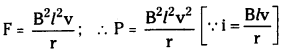
The work done is in the form of mechanical energy.
This is dissipated into the form of joule heat.
∴ Joule heat = Power Pj = I²r = \(\frac{B^2l^2v^2}{r}\)
![]()
Question 6.
What are Eddy currents? [TS Mar. ’19; AP June ’15]
Answer:
Eddy currents :
When large pieces of conductors are subjected to changing magnetic flux then current is induced in them. These induced currents are called ”Eddy currents”.
Eddy currents will oppose the motion of the coil (or) they oppose the change in magnetic flux.
Question 7.
Define ‘inductance’.
Answer:
Inductance :
The process of producing emf in a coil due to changing current in that coil or in a coil nearby it is called “Inductance”.
Flux associated with a coil ΦB is proportional to current i.e., ΦB ∝ I
This constant of proportionality is called Inductance.
Question 8.
What do you understand by ‘self induetance’? [AP & TS June ’15]
Answer:
Self inductance :
If emf is induced in a single isolated coil due to change of flux in that coil by means of changing current through that coil then that phenomenon is called “Self Inductance L”.
In Self inductance, ε = -L\(\frac{dI}{dt}\)
Short Answer Questions
Question 1.
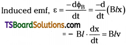
Obtain an expression for the emf induced across a conductor which is moved in a uniform magnetic field which is perpendicular to the plane of motion. [TS May ’16]
Answer:
Let a conductor of length T is moving with a velocity “v” in a uniform and time independent magnetic field B.
Consider a rectangular metallic frame PQRS in which the side PQ is free to move without friction.
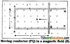
Let PQ move with a velocity ‘v’ in a perpendicular magnetic field B.
Magnetic flux in the loop ΦB = Bl . x, where x = RQ a time changing quantity.
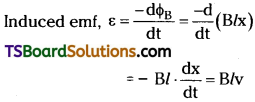
Here \(\frac{dx}{dt}\) = -v = Velocity of the rod.
Induced emf, ε = Blv is called Motional emf.
Question 2.
Describe the ways in which Eddy currents are used to advantage. [AP Mar. ’19, ’18, ’17, ’16, ’15, May ’18, ’17, ’16; TS Mar. ’18, ’15. May ’17]
Answer:
Advantages of Eddy currents:
- Electromagnetic breaking : In some electrically powered trains strong electromagnets are placed above rails. When these electromagnets are activated eddy currents induced in rails will oppose motion of train. These breaks are smooth.
- In galvanometers, a fixed core is made with non-magnetic material. When coil oscillates eddy currents induced in core will oppose the motion. As a result, the coil will come to rest quickly.
- In induction furnaces high frequency oscillating currents are passed through a coil which surrounds the metal to be melted. These currents will produce eddy currents in the metal and it is heated sufficiently to melt it.
- In electric power meters a metal disc is made to rotate due to eddy currents with some arrangement. Rotation of this disc is made to measure power consumed.
![]()
Question 3.
Obtain an expression for the mutual inductance of two long co-axial solenoids.
Answer:
Consider two long solenoids S1 and S2 each of length ‘l’, radius r1 and r2 and number of turns n1 and n2 respectively. When a current I2 is sent through S2 it will set up a magnetic flux Φ1 through S1.
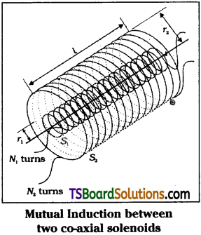
Flux linkage with S1 is N1 Φ1 = M12I2 where
M12 is mutual inductance between the coils.
But Φ1 = N1A1B where N1 = n1l ; A = πr²1 and B = µ0n2I2.
∴ N1Φ1 =(n1l)(πr²1 )(µ0n2I2) = µ0n1n2r²1 …………. (1)
This approximation is highly valid when l > > r2.
If current I1 is passed through S1 then
N2Φ2 = M21I1 where Φ2 = N2A2B and
B = µ0n1I1 and N2 = n2l.
∴ N2Φ2 =(n2l)(πr²1 )(µ0n1I1) = µ0n1n2πr²1l …………. (2)
From eq. (1) & (2) Mutual inductance bet-ween co-axial solenoids M12 = M21. If the solenoid is on a core of permeability µr then
[M12 = M21 = µ0µrn1n2πr²1l]
Mutual inductance of a pair of coils or solenoids etc., depends on seperation between them and also on their orientaton.
Question 4.
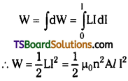
Obtain an expression for the magnetic energy stored in a solenoid in terms of the magnetic field, area and length of the solenoid.
Answer:
When current is passed through a single isolated coil or solenoid changing magnetic flux can be developed by changing current through it. This changing flux will induce emf in that coil.
This phenomenon is called self induction (L).
Flux linkage NΦB ∝ I or NΦB = L . I
Induced emf, ε = \(\frac{d}{dt}\)(NΦB) = -L\(\frac{dI}{dt}\) ………. (1)
– ve sign indicates that induced emf will always oppose the flux changes in that coil (or) solenoid.
Let length of solenoid is ‘l’, area of cross section = A
then NΦB = (nl)(µ0nI) (I) (∵ ΦB =nµ0I) ……….. (2)
and total number of turns N = n × l.
i.e., turns per unit length ‘n’ × length of solenoid ‘l’.
∴ L = \(\frac{\mathrm{N} \phi_{\mathrm{B}}}{\mathrm{I}}\) = µ0n²Al …………. (3)
This self induced emf also called back emf will oppose any change in current in the coil. So to drive current in the circuit we must do some work.
Rate of work done = \(\frac{dW}{dt}\) = |ε|I = LI.\(\frac{dI}{dt}\) …………. (4)
∴ Energy required to send the currrent or Energy stored in inductor
Long Answer Questions
Question 1.
Outline the path-breaking experiments of Faraday and Henry and highlight the contributions of these experiments to our understanding of electromagnetism.
Answer:
Faraday and Henry conducted a series of experiments to understand electromagnetic inductioin.
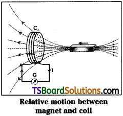
First Experiment:
In this experiment, a galvanometer is connected to a coil. A magnet is moved towards the coil. They observed that current is flowing in the coil when magnet is in motion.
The direction of induced current is in opposite direction when the direction of motion of magnet is changed.
So they concluded that relative motion between magnet and coil is responsible for generation of electric current in the coil.
Second Experiment:
In this experiment a steady current is passed through one coil with the help of a battery and the second coil is connected to a galvanometer. When one of the coil is moved then current is induced in the coil. This current losts as far as there is relative motion between them.
Again they concluded that relative motion between the coils is responsible for induced electric current.
Third Experiment:
In this experiment, they connected one coil to a battery and a tapping key to make and break electric contact in that coil. The second coil is placed near the first coil. When electric contact is established current is induced in the second coil and momentary deflection is observed in galvanometer.
When electric contact is breaked again they got deflection in galvanometer in opposite direction.
So they concluded that it is not the relative motion between the coil and magnet or relative motion between the coils that induces the current. The changing magnetic flux is responsible for induced emf or current in the coil.
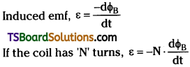
Finally Faraday proposed that induced emf ε = \(\frac{\mathrm{d} \phi_{\mathrm{B}}}{\mathrm{dt}}\) ⇒ ε = N.\(\frac{\mathrm{d} \phi_{\mathrm{B}}}{\mathrm{dt}}\)
But from Lenz’s explanation he corrected this equation as ε = –\(\frac{\mathrm{d} \phi_{\mathrm{B}}}{\mathrm{dt}}\) ⇒ ε = -N\(\frac{\mathrm{d} \phi_{\mathrm{B}}}{\mathrm{dt}}\)
![]()
Question 2.
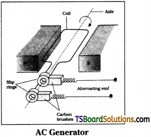
Describe the working of a AC generator with the aid of a simple diagram and necessary expressions.
Answer:
AC generator consists of a coil of N turns placed in a magnetic field B produced by magnetic poles when the coil is rotated its effective area changes so flux linked with the coil changes. This changing flux will induce emf in the coil.
Electric generator converts mechanical energy into electrical energy.
Flux associated with the coil,
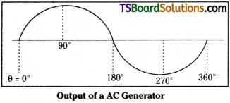
ΦB = (\(\overline{\mathrm{B}}\) • \(\overline{\mathrm{A}}\)) = BA cos θ, where θ = ωt
Induced emf, ε = -N\(\frac{\mathrm{d} \phi_{\mathrm{B}}}{\mathrm{dt}}\) = -NBA\(\frac{d}{dt}\)cos ωt
∴ Induced emf, ε = -NBAω sin ωt
The term NBAω is called maximum emf produced (εm).
∴ εm = NBAω
ε = εm sin ωt
Induced emf at any time E = εm sin ωt
When θ = 0, Induced emf is zero i.e., ε = 0.
The induced emf is maximum when θ = 90°
i.e., the plane of the coil is perpendicular
to magnetic field.
When θ = 90° ⇒ emf ε = εm
When θ = 180° ⇒ induced emf ε = 0.
When θ = 270° ⇒ induced emf ε = – εm.
again for θ = 360° ⇒ emf ε = 0.
∴ The induced emf varies sinusoidally in AC generator.
The coil is mounted on a rotor shaft. The axis of rotation of coil is perpendicular to magnetic field. The coil is connected to external circuit by means of slip rings and brushes.
Induced emf at any time is given by ε = εm sin ωt = εm sin 2πυt.
Depending on the method of supplying mechanical energy to rotate shaft these AC generators are classified as 1) Hydroelectric generators, 2) Thermal generators and 3) Nuclear generators.
Exercises
Question 1.
Obtain an expression for the emf induced across a conductor which is moved in a uniform magnetic field which is perpendicular to the plane of motion. [AP May ’14]
Answer:
Let a conductor of length ‘l’ is moving with a velocity “v” in a uniform and time independent magnetic field B.
Consider a rectangular metallic frame PQRS in which the side PQ is free to move without friction.
Let the wire PQ is moved with a velocity ‘v’ in a perpendicular magnetic field B.
Magnetic flux in the loop ΦB = Bl . x, where x = RQ a time changing quantity.
Here \(\frac{dx}{dt}\) = -v = Velocity of the rod.
Induced emf, ε = Blv is called Motional emf.
Question 2.
Current in a circuit falls from 5.0 A to 0.0 A in 0.1 s. If an average emf of 200 V induced, give an estimate of the self inductance of the circuit. [AP Mar. 14; TS Mar. 16]
Answer:
Initial current, I1 = 5.0 A ;
Final current, I2 = 0.0 A ;
Change in current, dl = I1 – I2 = 5 A
Time taken for the change, t = 0.1 s;
Average emf, ε = 200 V
For self-inductance (L) of the coil, we have the relation for average emf as
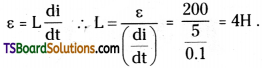
Hence, the self induction of the coil is 4H.
Question 3.
A pair of adjacent coils has a mutual inductance of 1.5 H. If the current in one coil changes from 0 to 20 A in 0.5 s, what is the change of flux linkage with the other coil? [TS May ’18, Mar. ’17]
Answer:
Mutual inductance of a pair of coils, µ = 1.5 H;
Initial current, I1 = 0 A
Final current I2 = 20 A ;
Change in current, dl – I2 – I1 = 20 – 0 = 20 A
Time taken for the change, t = 0.5 s
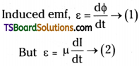
Where dΦ is the change in the flux linkage with the coil.
Equating equations (1) and (2), we get
\(\frac{\mathrm{d} \phi}{\mathrm{dt}}\) = µ\(\frac{dI}{dt}\) ; dΦ = 1.5 × (20) = 30 Wb
Hence, the change in the flux linkage is 30 Wb.
![]()
Question 4.
A jet plane is travelling towards west at a speed of 1800 km/h. What is the voltage difference developed between the ends of the wing having a span of 25 m, if the Earth’s magnetic field at the location has a magnitude of 5 × 10⁻⁴ T and the dip angle is 30°.
Answer:
Speed of the jet plane, v = 1800 km/h = 500 m/s ;
Wing span of jet plane, l = 25 m
Earth’s magnetic field strength,
B = 5.0 × 10⁻⁴ T ; Angle of dip, δ = 30°
Vertical component of Earth’s magnetic field,
Bv = B sin δ = 5 × 10⁻⁴ sin 30° = 2.5 × 10⁻⁴T
Voltage difference between the ends of the wing can be calculated as
ε = (Bv) × l × v = 2.5 × 10-4 × 25 × 500 = 3.125 V
Hence, the voltage difference developed between the ends of the wings is 3.125 V.