Telangana TSBIE TS Inter 2nd Year Physics Study Material 10th Lesson Alternating Current Textbook Questions and Answers.
TS Inter 2nd Year Physics Study Material 10th Lesson Alternating Current
Very Short Answer Type Questions
Question 1.
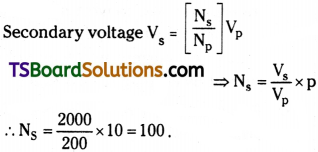
A transformer converts 200 V ac into 2000 V ac. Calculate the number of turns in the secondary if the primary has 10 turns. [TS Mar. ’16; AP Mar. 19, ’18] [IMP]
Answer:
Primary voltage Vp = 200 V ;
Secondary voltage Vs = 2000 V
Number of turns in Primary Np = 10 ;
Number of turns in Secondary = Ns = ?
Question 2.
What type of transformer is used in a 6V bed lamp? [AP Mar. ’17]
Answer:
6V Bed lamp ⇒ Vs = 6V. But our mains supply is 220V (called primary voltage Vp).
So Vs < Vp.
Hence transformer used in bed lamp is step down transformer.
Question 3.
What is the phenomenon involved in the working of a transformer? [AP May ’18, ’17, ’16; Mar. ’16, ’14; June ’15]
Answer:
A transformer uses the principle of “mutual Induction”.
It also obeys law of conservation of energy.
In a transformer VpIp = VsIs.
Question 4.
What is transformer ratio? [TS May ’18]
Answer:
The ratio of number of turns in secondary (Ns) to number of turns in primary (Np) is called “transformer turns ratio”.
Transformer turns ratio = \(\frac{N_s}{N_p}\)
Question 5.
What is the phase difference between A.C. emf and current in the following? Pure resistor and pure inductor. [TS Mar. ’15]
Answer:
- In pure resistor AC emf and current are in same phase.
∴ Phase difference f = 0. - In pure inductor current lags behind emf by a phase angle Φ = 90° or \(\frac{\pi}{2}\) radians.
- In pure capacitor current leads emf by a phase angle f = 90° or \(\frac{\pi}{2}\) radians.
![]()
Question 6.
What is Step-up transformer? How it differs from Step-down transformer?
Answer:
A Step-up transformer will convert low voltage input into high voltage output.
A Step-down transformer will convert high voltage input into low voltage output.
Question 7.
Write the expression for the reactance of (I) an inductor and (ii) a capacitor.
Answer:
- Reactance of an Inductor XL = ωL
- Reactance of Capacitor Xc = \(\frac{1}{\omega C}\)
Where ω = 2πυ is the angular frequency of applied voltage.
Question 8.
What is the phase difference between AC emf and current in the following : Pure resistor, pure inductor and pure capacitor. [TS Mar. ’15]
Answer:
- In pure resistor AC emf and current are in same phase.
∴ Phase difference Φ = 0. - In pure inductor current lags behind emf by a phase angle Φ = 90° or \(\frac{\pi}{2}\) radians.
- In pure capacitor current leads emf by a phase angle Φ = 90° or \(\frac{\pi}{2}\) radians.
Question 9.
Define power factor. On which factors does power factor depend?
Answer:
Power of AC circuit and power factor :
Power of AC circuit P = I²Z cos Φ. It indicates that power depends not only on current I and Impedance Z of circuit, but also cosine of phase angle between I and Z.
The term cos Φ is called power factor.
Question 10.
What is meant by wattless component of current? [TS Mar. ’17]
Answer:
Wattless current :
In a circuit with pure inductance or pure capacitance the phase angle between voltage and currents are Φ= \(\frac{\pi}{2}\) , so cos Φ = 0. Hence no power is dissipated through then even though current passes through them. This current is referred as wattless current.
![]()
Question 11.
When does a LCR series circuit have minimum impedance?
Answer:
Impedance of series LCR circuit
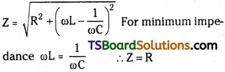
In series LCR circuit Impedance is minimum at Resonance condition.
Question 12.
What is the phase difference between voltage and current when the power factor in LCR series circuit is unity?
Answer:
Power in a circuit P = VI cos Φ
Power factor is unity cos Φ = 1 ⇒ Φ = 0°
∴ Phase difference between voltage and current Φ = 0.
Short Answer Questions
Question 1.
Obtain an expression for the current through an inductor when an AC emf is applied.
Answer:
Let an inductor (L) of negligible resistance is connected in an AC circuit. This is treated as purely inductive circuit.
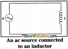
Voltage applied V = Vm sin ωt
From Kirchhoff’s loop rule
V – L \(\frac{di}{dt}\) = 0 → (1) Because induced emf
ε = – L\(\frac{di}{dt}\) is in opposite direction.
∴ \(\frac{di}{dt}=\frac{V}{L}=\frac{v_m}{L}\) sin ωt → (2)
Total current through inductor
ωL is the reactance offered by inductor for the flow of current in circuit.
Reactance of Inductor XL = ωL, similar to Resistance.
In a pure inductor current, I lags behind applied voltage V by an angle Φ = 90° or \(\frac{\pi}{2}\) radians.
Question 2.
Obtain an expression for the current in a capacitor when an AC emf is applied.
Answer:
Let an ac voltage V = Vm sin cot is applied across the plates of a capacitor. Then charge begin to accumulate on the capacitor plates then gradually its voltage increases.
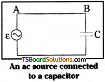
By using ac voltage the capacitor will be charged and discharged alternately due to reversal of current in each half cycle.
Potential on capacitor V = \(\frac{q}{C}\) → (1)
But V = Vm sin ωt
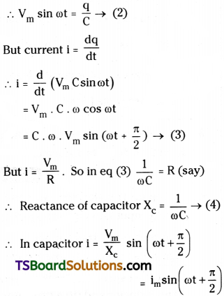
In a capacitor current in circuit leads the applied voltage by an angle Φ = 90° or \(\frac{\pi}{2}\) radians.
![]()
Question 3.
State the principle on which a transformer works. Describe the working of a transformer with necessary theory.
Answer:
Principle :
A transformer works on the principle of Mutual induction.
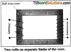
A transformer consists of two coils wound on a core made with soft iron.
The coil which is connected to mains supply is called primary coil. Let number of turns in primary are say Np. The coil through which output is taken is called secondary coil. Let number of turns in secondary are say Ns.
Induced emf in secondary
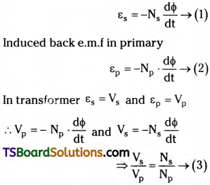
Ratio of turns in secondary to primary \(\frac{N_s}{N_p}\) is called transformer turns ratio.
In a transformer output voltage Vs (\(\frac{N_s}{N_p}\))Vp → (4)
If Vs > Vp it is called step up transformer.
Vs < Vp it is called step down transformer.
The equation Vs = \(\frac{N_s}{N_p}\)Vp is applicable for Ideal transformers. But in real case a small amount of energy (less than 5%) is wasted due to 1) Flux leakage 2) Resistance of windings 3) Eddy currents and 4) Hysteresis,
Long Answer Questions
Question 1.
Obtain an expression for impedance and current in series LCR circuit. Deduce an expression for the resonating frequency of an LCR series resonating circuit.
Answer:
In series LCR circuit an inductance ‘L’, capacitance ‘C’ and a resistance ‘R’ are connected in series with an ac source.
Let voltage applied, V = Vm sin ωt → (1)
In series combination, total voltage in circuit is sum of voltage drops on each component
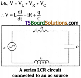
Here VL and Vc are always in same phase but in opposite direction.
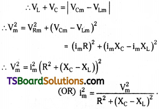
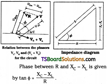
The term R² + (XC – XL)² is called impedance Z’. Its behaviour is like Resistance R in DC circuit.
The phasor diagram of VR, Vc and VL are as shown.
Resonating frequency :
Resonance is a physical phenomenon at which a system tends to oscillate freely. This particular frequency is called Resonating frequency.
The reactance of Inductance XL = ωL and
Reactance of capacitance Xc = \(\frac{1}{\omega C}\) opposite in nature.
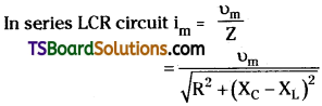
When XC = XL then impedance Z = R has lowest value and current in LCR circuit is
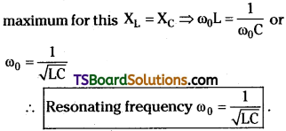
(At resonating frequency potential across ‘L’ and potential across ‘C’ will cancell each other.
At resonance current in series LCR circuit is maximum im = \(\frac{V_m}{Z}=\frac{V_m}{R}\).)
Problems
Question 1.
A transformer converts 200 Vac into 2000 V ac. Calculate the number of turns in the secondaryif the primary has 10 turns.
Solution:
V1 = 200 V, V2 = 2000 V, n1 = 10, n2 = ?
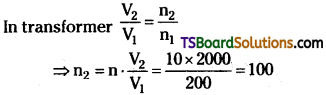
∴ Number of turns on secondary n2 = 100.
Question 2.
An ideal inductor (no internal resistance for the coil) of 20 mH is connected in series with an AC ammeter to an AC source whose emf is given by e = 20√2 sin(200t + π/3) V, where t is in seconds. Find the reading of the ammeter.
Solution:
Inductance L = 20 mH = 20 × 10-3H
emf. e = 20√2 sin (200t + \(\frac{\pi}{3}\))V.
From standard equation e = em sin (ωt + Φ)
Maximum voltage em = 20√2 V
Average voltage = \(\frac{e_{\mathrm{m}}}{\sqrt{2}}=\frac{20 \sqrt{2}}{\sqrt{2}} \) = 20 V.
Impedance, ZL = ωL. But ω = 200
∴ ZL = 200 × 2 × 10-3 = 4
Instantaneous current 1 = \(\frac{e}{Z}=\frac{20}{4}\) = 5A.
![]()
Question 3.
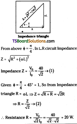
The instantaneous current and instantaneous ( voltage across a series circuit containing resistance and inductance are given by i = √2 sin (100t – π/4) A and V = 40 sin (100t) V. Calculate the resistance.
Solution:
Instantaneous current I = √2 sin(100t + \(\frac{\pi}{4}\))A
Instantaneous voltage V = 40 sin (100t) V
Question 4.
In an AC circuit, a condenser, a resistor and a pure inductor are connected in series across an alternator (AC generator). If the voltages across them are 20 V, 35 V and 20 V respectively, find the voltage supplied by the alternator.
Solution:
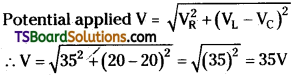
Voltage across Condenser VC = 20 V
Voltage across Resistor VR = 35 V
Voltage across Inductor VL = 20V
In LCR circuit total potential difference =
Question 5.
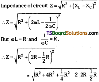
An AC circuit contains a resistance R, an inductance L and a capacitance C connected in series across an alternator of constant voltage and variable frequency. At resonant frequency, it is found that the inductive reactance, the capacitive reactance and the resistance are equal and the current in the circuit is ifl. Find die current in the circuit at a frequency twice that of the resonant frequency.
Solution:
In LCR circuit at resonance Impedance Z = R
Current at resonance i0 = \(\frac{V_0}{Z}=\frac{V_0}{R}\)
Reactance of inductor XL = ωL and
Reactance of condenser XC = – \(\frac{1}{\omega C}\)
When frequency is doubled (say ω1 = 2ω)
XL = 2 . ωL and XC = \(\frac{1}{2\omega C}\)
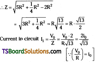
Question 6.
A series resonant circuit contains L1, R1 and C1. The resonant frequency is f. Another series resonant circuit contains L2, R2 and C2. The resonant frequency is also f. If these two circuits are connected in series, calculate the resonant frequency.
Solution:
For first series LCR circuit
C = C1, L = L1 and R = R1 and resonant
frequency f = \(\frac{1}{\sqrt{L_1 C_1}}\)
For second series LCR circuit
L = C2, C = C2 and R = R2 resonant frequency f = \(\frac{1}{\sqrt{L_2 C_2}}\)
Given that f1 = f2 and two circuits are again in series with source.
In series combination same AC current will flow with same frequency through all the parts.
Circuits 1 and 2 are at resonance with the applied frequency f.
So when the two LCR circuits of same resonant frequency are connected in series still then there is no change in resonant frequency.
Question 7.
In a series, LCR circuit R = 200 Ω and the voltage and the frequency of the mains supply is 200 V and 50 Hz respectively. On taking out the capacitance from the circuit the current lags behind the voltage by 45°. On taking out the inductor from the circuit the current leads the voltage by 45°. Calculate the power dissipated in the LCR circuit.
Solution:
Given Resistance R = 200 Ω,
Voltage V = 200 V, Frequency u = 50 Hz.
When capacitor is removed current lags behind voltage by 45°
When Inductance is removed current leads voltage by 45°.
From above statements, the circuit is at resonance.
At resonance power dissipated P = \(\frac{V^2}{R}=\frac{200\times200}{200}\) = 200 W
![]()
Question 8.
The primary of a transformer with primary to secondary turns ratio of 1 : 2, is connected to an alternator of voltage 200 V. A current of 4 A is flowing though the primary coil: Assuming that the transformer has no losses, find the secondary voltage and current are respectively.
Solution:
Turns ratio of primary to secondary np : ns = 1 : 2
Input voltage V1 = 200 V, Input current Ii = 4A
Output voltage V0 = Vi \(\frac{Ns}{np}\) = 200 × 2 = 400 V
In transformer V I = constant i.e., Vi.Ii = V0I0
∴ Output current I0 = \(\frac{V_iI_i}{V_0}=\frac{200\times4}{400}\) = 2A
Exercises
Question 1.
A 100 Ω resistor is connected to a 220 V, 50 Hz ac supply.
a) What is therms value of current in the circuit?
b) What is the net power consumed over a full cycle?
Answer:
Resistance R = 100 Ω ; Voltage, V = 220 V; Frequency, υ = 50 Hz.
a) The rms value of current in the circuit is given as:
I = \(\frac{V}{R}=\frac{220}{100}\) = 2.20A
b)The net power consumed over a full cycle is given as:
P = VI ⇒ p = 220 × 2.2 = 484 W
Question 2.
a) The peak voltage of an ac supply is 300 V. What is the rms voltage?
b) The rms value of current in an ac circuit is 10 A. What is the peak current?
Answer:
a) Peak voltage of the ac supply, V0 = 300 V
Rmsvoltage V = \(\frac{V_0}{\sqrt{2}}=\frac{300}{\sqrt{2}}\) = 212.1 V
b) The rms value of current I = 10 A Now, peak current
I0 = √2I = 10√2 = 14.1 A
Question 3.
A 44 mH inductor is connected to 220 V, 50 Hz ac supply. Determine the rms value of the current in the circuit
Answer:
Inductance of inductor, L = 44 mH = 44 × 10-3 H ;
Supply voltage, V = 220 V
Frequency, υ = 50 Hz ;
Angular frequency, ω = 2πυ
Inductive reactance, XL = ωL = 2πυL
= 2π × 50 × 44 × 10-3Ω
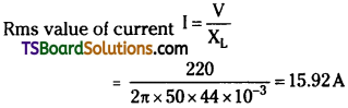
Hence, the rms value of current in the circuit is 15.92 A.
Question 4.
A 60 µF capacitor is connected to a 110V, 60Hz ac supply. Determine the rms value of the current in the circuit.
Answer:
Capacitance of capacitor, C = 60 µF
= 60 × 10-3 F;
Supply voltage, V = 110 V
Frequency, υ = 60 Hz;
Angular frequency, ω = 2πυ
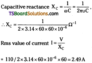
Hence, the rms value of current is 2.49 A.
![]()
Question 5.
Obtain the resonant frequency ωr of a series LCR circuit with L = 2.0 H, C = 32 µF, and R = 10Ω. What is the Q-value of this circuit?
Answer:
Inductance, L = 2.0 H;
Capacitance, C = 32 µF = 32 × 10-6 F
Resistance, R = 10 W ; Resonant frequency
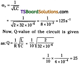
Hence, the Q-Value of this circuit is 25.
Question 6.
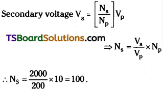
A transformer converts 200 Vac into 2000 V ac. Calculate the number of turns in the secondary coil if the primary coil has 10 turns.
Answer:
Primary voltage Vp = 200 V
Secondary voltage Vg = 2000 V
Number of turns in Primary Np = 10
Number of turns in Secondary = Ns = ?
Question 7.
A charged 30 pF capacitor is connected to a 27 mH inductor. What is the angular frequency of free oscillations of the circuit?
Answer:
Capacitance, C = 30µF = 30 × 10-6 F;
Inductance, L = 27 mH = 27 × 10-3H
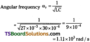
Hence, the angular frequency of free oscillations of the circuit is 1.11 x 10³ rad/s.
![]()
Question 8.
Suppose the initial charge on the capacitor in Exercise 7 is 6 mC. What is the total energy stored in the circuit initially? What is the total energy at later time?
Answer:
Capacitance of the capacitor, C = 30 µF
= 30 × 10-6F ;
Inductance of the inductor, L = 27 mH
= 27 × 10-3 H ;
Charge on the capacitor, Q = 6 mC = 6 × 10⁻³ C
Total energy stored in the capacitor E = \(\frac{1}{2}\frac{Q^2}{C}\)
Total energy at a later time will remain the same because energy is shared between the capacitor and the inductor.