Telangana TSBIE TS Inter 2nd Year Physics Study Material 7th Lesson Moving Charges and Magnetism Textbook Questions and Answers.
TS Inter 2nd Year Physics Study Material 7th Lesson Moving Charges and Magnetism
Very Short Answer Type Questions
Question 1.
What is the importance of Oersted’s experiment? [AP May ’18; TS Mar. ’17, May ’14]
Answer:
Oersted concluded that moving charges (or) currents produces a magnetic field in the surrounding space.
Question 2.
State Ampere’s law and Biot – Savart law.
Answer:
Ampere’s circuital law :-
The total magnetic flux coming out of a current carrying conductors enclosed in a perpendicular plane is p0 times greater than the alzebraic sum of currents (Iencl) enclosed by all the conductors in that plane.
\(\oint \mathrm{B} . \mathrm{d} l=\mu_0 \mathrm{I_{encl}}\)
Biot – Savart’s Law :
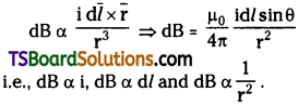
The magnetic field (dB) due to a current carrying element (dl) at any point r from the conductor is given by
Question 3.
Write the expression for the magnetic induction at any point on the axis of a circular current – carrying coil. Hence, obtain an expression for the magnetic induction at the centre of the circular coil.
Answer:
(i) Magnetic induction of any point x on the axis of a coil of radius (R) is
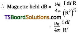
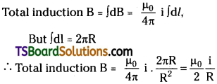
(ii) At centre of the coil (x = 0);
Question 4.
A circular coil of radius ‘r’ having N turns carries a current “i”. What is its magnetic moment?
Answer:
Magnetic induction at the centre of the coil
B = \(\frac{\mu_0}{2} \frac{\mathrm{i}}{\mathrm{R}}\)
For n turns the total magnetic field = (n times more)
∴ B = \(\frac{\mu_0}{2} \frac{\mathrm{ni}}{\mathrm{R}}\)
Question 5.
What is the force on a conductor of length L carrying a current “i” placed in a magnetic field of induction B? When does it become maximum?
Answer:
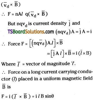
Let a conductor of length L’ and current i through it is placed in a magnetic field B then force on it F = i (\(\overline{\mathrm{L}}\times\overline{\mathrm{B}}\)) = i LB sin θ where θ = the angle between the length of conductor (L) and magnetic field direction \(\overline{\mathrm{B}}\). Force on current carrying conductor is maximum when tlie conductor makes an angle θ = 90° with magnetic field (Fman) = iLB.
![]()
Question 6.
What is the force on a charged particle of charge “q” moving with a velocity “v” in a uniform mangnetic field of induction B? When does it become maximum?
Answer:
Let a charge q is moving with a velocity v in a magnetic field B then force on the charged particle F = q(\(\overline{\mathrm{v}}\times\overline{\mathrm{B}}\)) =q\(\overline{\mathrm{v}}\)B sin θ. Where ‘θ’ is the angle between the direction of velocity (\(\overline{\mathrm{v}}\)) and direction of magnetic field (\(\overline{\mathrm{B}}\)).
Force on charged particle is maximum when it moves perpendicular to the magnetic field.
i. e., when θ = 90° ⇒ Fmax = qvB
Question 7.
Distinguish between ammeter and voltmeter. [AP Mar. 18, 17, 15; May 17, 16; TS June 15]
Answer:
| Ammeter | Voltmeter |
| 1. It is used to measure current in a circuit. | 1. It is used to measure potential difference between two points. |
| 2. Its resistance must be low. | 2. Its resistance must be high. |
| 3. It is connected in series in the circuit. | 3. It is connected in parallel between given points. |
Question 8.
What is the principle of a moving coil galvanometer? [TS May ’16]
Answer:
Principle of moving coil galvanometer :
When a current carrying coil placed in a radial magnetic field is free to rotate then torque acting on it is τ = NIAB.
In M. C. G deflection torque (τ = NIBA) is produced by the current in the coil. Restoring torque is produced by torsional constant (K) of the spring. At equilibrium deflection θ = (\(\frac{NAB}{k}\))I
Question 9.
What is the smallest value of current that can be measured with a moving coil galvanometer?
Answer:
The smallest value of current that can be measured with moving coil galvanometer is in the order of 10-6 to 10-12 amperes.
Generally galvanometers will give full scale deflections for few micro amperes (µA)
Question 10.
How do you convert a moving coil galva-nometer into an ammeter? [AP Mar. 19, May 18, June 15; TS May 18, Mar. 18]
Answer:
A M.C.G is converted into an ammeter by connecting a low resistance (shunt) in parallel to it.
Shunt S = \(\frac{RG}{n-1}\) where RG = Resistance of galvanometer.
n = Ratio of currents \(\frac{i}{ig}\)
Question 11.
How do you convert a moving coil galvanometer into a voltmeter? [AP May. 18. Mar. 16, 15; TS Mar. 16. 15]
Answer:
A M.C.G can be converted into a voltmeter by connecting a high resistance in series with it.
Series resistance Rs = (V/ig – RG)
V = Potential to be measured; i = maximum current through M.C.G
Rg = Resistance of M.C.G
Question 12.
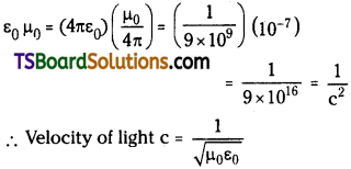
What is the relation between the permittivity of free space ε0, the permeability of free space µ0, and the speed of light in vacuum?
Answer:
Relation between permittivity of free space ε0 and permeability of free space µ0is
Question 13.
A current carrying circular loop lies on a smooth horizontal plane. Can a uniform magnetic field be set up in such a manner that the loop turns about the vertical axis?
Answer:
No.
Question 14.
A current carrying circular loop is placed in a uniform external magnetic field. If the loop is free to turn, what is its orientation when it is achieves stable equilibrium?
Answer:
When a current carrying loop is placed in a uniform magnetic field the most stable state of equilibrium is magnetic moment of the loop (\(\overline{\mathrm{m}}\) = iA) and magnetic field \(\overline{\mathrm{B}}\) are parallel to each other, (i.e., θ = 0 between \(\overline{\mathrm{m}}\) and \(\overline{\mathrm{B}}\))
![]()
Question 15.
A wire loop of irregular shape carrying current is placed in an external magnetic field. If the wire is flexible, what shape will the loop change to? Why?
Answer:
If a flexible wire loop carrying current is placed in an external magnetic field it will attain circular shape.
Due to flow of charges (i.e., current) in the loop a force F = Bqv is acting at every point of flexible loop. So it attains circular shape.
Short Answer Questions
Question 1.
State and explain Biot – Savart’s law. [AP Mar. 18. 17, 16, May 14; TS Mar. 17, 16]
Answer:
According to Biot – Savart’s Law,
- The magnitude of magnetic field dB is proportional to the current [dB α I]
- Magnetic field dB is proportional to length of current carrying element [dB α dl]
- Since of the angle between the current carrying element and the line joining the midpoint of the element and the given point and
- Magnetic field dB is inversely proportional to the square of the distance ‘r’ of given point from the current carrying element dB α \(\frac{1}{r^2}\).
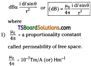
2) θ = the angle between the current carrying element d/ and the line joining the conductor and the given point.
Question 2.
State and explain Ampere’s law. [TS Mar. ’18]
Answer:
Ampere’s law :
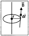
The magnetic field lines emerging out of a long straight current carrying conductor are in the form of anti clock wise concentric circles with the wire at their centre.
The magnetic field emerging out through a small element dl is given by \(\overline{\mathrm{B}} \cdot \mathrm{d} \bar{l}=\overline{\mathrm{B}} \cdot \mathrm{d} \bar{l} \cos \theta\)
![]()
Here B and d/ are parallel to each other, so cos θ = 1.
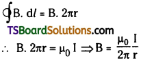
Total magnetic field due to the entire loop \(\oint \mathrm{B} . \mathrm{d} l=\mu_0 \mathrm{i}\)
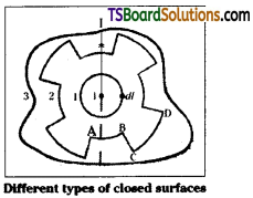
Ampere’s circuital Law :
Total magnetic field coming out of a current carrying conductor in a perpendicular plane is times greater than the current flowing through it.
- If there are number of conductors ‘n’ in an enclosure then i is the alzebraic sum of currents in that enclosure and total magnetic field \(\oint \mathrm{B} . \mathrm{d} l=\mu_0 \mathrm{I_{encl}}\)
- Ampere’s circuital law is valid to a closed loop of any shape.
Question 3.
Find the magnetic induction due to a long current carrying conductor. [AP June ’15]
Answer:
Consider a long straight conductor perpendicular to plane of paper, carrying a current I. Then the magnetic field lines emerging out of the conductor are in the plane of the paper. These magnetic field lines will form concentric circles with the conductor at the centre.
Take a small element d/ on the circle which is at a distance ‘r’ from the wire \(\overline{\mathrm{B}} \cdot \mathrm{d} \bar{l}\)
= B dl cos θ where (\(\overline{\mathrm{B}}\)) and d\(\overline{\mathrm{l}}\) are in same direction. (θ = 0°)
Total magnetic field due to a straight current carrying conductor B = \(\oint \mathrm{B} . \mathrm{d} l=\mu_0 \mathrm{I}\)
From Ampere’s law total magnetic field = µ0 I
∴ Magnetic field of any point due to a straight current carrying conductor B = \(\frac{\mu_0}{2 \pi} \frac{I}{r}\)
Question 4.
Derive an expression for the magnetic induction at the centre of a current carry-ing circular coil using Biot – Savart’s law. [TS May ’16]
Answer:
Consider a circular loop of radius ‘R’ carrying a current i. P is a point on the axis of the coil (say X – axis).
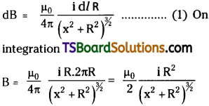
From Biot – Savart’s law magnetic field at any point can be written as
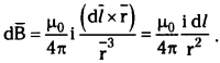
Element d/ is on Y axis and point P is in XY – plane.
∴ \(|\mathrm{d} \bar{l} \times \overline{\mathbf{r}}|\) = rdl
The magnetic field at ‘P’ makes some angle ‘θ’ with X – axis. So resolve d \(\overline{\mathrm{B}}\) into two perpendicular components say d\(\overline{\mathrm{B}}_{x}\) and d \(\overline{\mathrm{B}}\)⊥. Sum of d\(\overline{\mathrm{B}}\)⊥ is zero. Because d\(\overline{\mathrm{B}}\)⊥ component by an element d/ is cancelled by another diametrically opposite component.
Question 5.
Derive an expression for the magnetic induction (B) at a point on the axis of a current carrying circular coil using Biot – Savart’s law. [TS May ’16]
Answer:
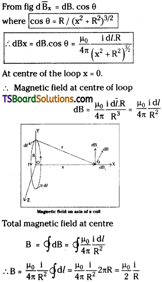
Consider a circular loop of radius ‘R’ carrying a current i and P is a point on the axis of the coil (say X – axis).
From Biot – Savart’s law magnetic field at
The magnetic field at ‘P’ makes some angle ‘0’ with X – axis. So resolve d\(\overline{\mathrm{B}}\) into two perpendicular components say d\(\overline{\mathrm{B}}_{x}\) and d\(\overline{\mathrm{B}}\)⊥. Sum of d\(\overline{\mathrm{B}}\)⊥ is zero. Because d\(\overline{\mathrm{B}}\)⊥ component by an element dl is cancelled by another diametrically opposite component. From fig d\(\overline{\mathrm{B}}_{x}\) = dB. cos θ. Where

Question 6.
Obtain an expression for the magnetic dipole moment of a current loop.
Answer:
Let a rectangular loop of length ‘l’, breadth ‘b’ is placed in a uniform magnetic field B. Let a current I is passed through the loop. Now force on each side F1 = F2 = I b. B
Current passes through the loop in opposite direction, so F1 and F2 are opposite. So F1 and F2 forms a couple.
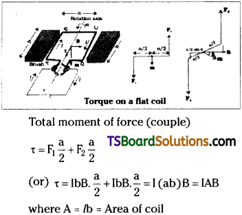
Let the coil is rotated by an angle θ then the perpendicular distance between F and B is a/2 cos θ.
∴ Total torque
τ = IbB.\(\frac{a}{2}\)sin θ + IbB.\(\frac{a}{2}\)sinθ = I(ab)B sinθ = IAB sinθ
Torque τ = moment of force couple = Force x ⊥lr distance
Here we are defining a new term called a magnetic dipole moment of the loop \(\overline{\mathrm{m}}\) = IA.
∴ Torque τ = \(\overline{\mathrm{mB}}\)sinθ = \(\overline{\mathrm{m}}\times\overline{\mathrm{B}}\)
This is similar to torque τ = \(\overline{\mathrm{r}}\times\overline{\mathrm{F}}\)
∴ Magnetic dipole moment \(\overline{\mathrm{m}}\) = IA for a loop of one turn.
\(\overline{\mathrm{m}}\) = nIA for a coil of n turns.
![]()
Question 7.
Derive an expression for the magnetic dipole moment of a revolving electron. [AP Mar. ’16]
Answer:
Let an electron (e) be revolving around the nucleus in a circular path of radius r’. Current I = number of electrons flowing per second.
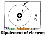
Dipolement ot electron
Let time period of revolution of electron = T
Then current I = \(\frac{e}{T}\) But T = \(\frac{2\pi r}{υ}\)
∴ I = eν/2πr
Magnetic moment is associated with a circulating current in a loop or closed path. Magnetic moment (M) = IA.
Here magnetic moment is represented by µr.
![]()
The direction of this magnetic moment is into the plane of the paper.
Question 8.
Explain how crossed E and B fields serve as a velocity selector.
Answer:
Let a charge ‘q’ is moving with a velocity in the presence of both electric field E and magnetic field B. Let these two fields are perpendicular to each other and also perpendicular to the velocity of the particle.
Force due to electric field FE = qE
Force due to magnetic field FB = qvB
Let the two fields are adjusted such that force applied by the two fields are equal and opposite. Then total force on the charged particle is zero.
Now qE = qvB (or) v = \(\frac{E}{B}\)
∴ Velocity of charged particle (v) is the ratio of strength of electric field E and magnetic field B.
So crossed electric field E and magnetic field B will serve as a velocity selector because only particles with a velocity v = \(\frac{E}{B}\) will pass undeflected through crossed electric and magnetic fields.
Question 9.
What are the basic components of a cyclotron? Mention its uses? [AP May ’16]
Answer:
Cyclotron is used to accelerate the charged particles.
The main parts of cyclotron are
- ‘D’ shaped metal boxes called dees
- Variable electric field
- Variable magnetic field and
- A Radio frequency oscillator.
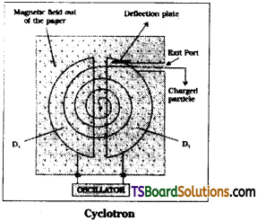
1) Dees : Two ‘D’ shaped metal boxes are placed side by side with a small gap between them. An exit port is provided to one of the Dee’.
2) Electric field E is useful to accelerate the charged particles in the gap between the dees, electric field is shield by the metallic dees. Inside D’ there is no effect of electric field.
3) Magnetic field B is used to rotate the charged particle. In magnetic field B time
m = mass of charged particle ;
q = charge on particle
Time period T is independent of velocity of the particle.
4) Radio frequency oscillator is used to obtain resonance condition. When frequency of applied voltage (Va) is equal to frequency of cyclotron υc then cyclotron is said to be in resonance condition. By adjusting phase difference between dees the charged particles can be accelerated upto required energy. Kinetic energy of charged particle depends on its velocity ‘v’.
Long Answer Questions
Question 1.
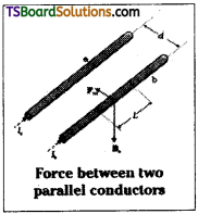
Deduce an expression for the force on a current carrying conductor placed in a magnetic field. Derive an expression for the force per unit length between two parallel current carrying conductors.
Answer:
Consider a rod of uniform cross section A and length ‘l’. Let the density of the mobile charge carriers per unit volume is ‘n’.
For a steady current i the total number of mobile charge carriers in it nAl.
Let average drift velocity of each charge = vd
When this conductor is placed in a magnetic field B. Force on it F = total charge
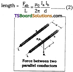
Force between two long parallel conductors :
If two long conductors ‘a’ and ‘b’ are carrying the currents Ia and Ib. Separated by the distance ‘d’. Conductor ‘A’ produces a magnetic field Ba at all points along conductor ‘B’ due to the current flowing through it.
Magnetic field due to ‘A’ = Ba = \(\frac{\mu_0}{2\pi } \frac{\mathrm{I_a}}{\mathrm{d}}\) …………… (1)
Conductor ‘B’ carrying a current Ib is in the magnetic field produced by ‘A’. Force acting on conductor ‘B’ due to ‘A’ is Fba = Ib L Ba = \(\frac{\mu_0}{2\pi } \frac{\mathrm{I_aI_b}}{\mathrm{d}}\).L
Where L is length of conductor ‘B’.
Now conductor ‘A’ is in the magnetic field produced by ‘B’.
Force due to ‘B’ on ‘A’ = Fab.
From Newton’s 3rd law Fab = – Fba
∴ Force between two parallel conductors Fab = Fba = \(\frac{\mu_0}{2\pi } \frac{\mathrm{I_aI_b}}{\mathrm{d}}\).L
∴ Force between parallel conductors per unit lenght = \(\frac{F_{ab}}{L }=\frac{\mu_0}{2\pi } \frac{\mathrm{I_aI_b}}{\mathrm{d}}\) ……….. (2)
![]()
Question 2.
Obtain an expression for the torque on a current carrying loop placed in a uniform magnetic field. Describe the construction and working of a moving coil galvanometer.
Answer:
Let a rectangular loop of length b’, breadth a’ is placed in a uniform magnetic field B. Let a current I is passed through the loop. Now force on each side F1 = F2 = I b. B
Current passes through the loop in opposite direction so F1 and F2 are opposite. So F1 and F2 forms a force couple.
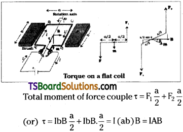
Where A = ab = Area of coil
Let the coil is rotated by an angle 0 then the perpendicular distance between F and B is a/2 sinG.
∴ Total torque τ = IbB\(\frac{a}{2}\) sinθ + IbB.\(\frac{a}{2}\) sinθ = I(ab)B sinθ = IAB sinθ
∴ Torque on a coil placed in a magnetic field τ = IAB sinθ
Construction and working of a moving coil galvanometer :
A moving coil galvanometer consists of a rectangular coil of n’ turns. It is placed in a uniform radial magnetic field. So \(\overline{\mathrm{B}}\) is perpendicular to area vector \(\overline{\mathrm{A}}\).
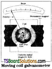
Hence torque is maximum.
Torque on coil τ = NiAB
This torque tends to rotate the coil. So it is called deflecting torque. A spring attached to the coil will provide the restoring torque. At equilibrium deflection (say Φ) is given by kΦ = NIAB (or) Φ = \(\frac{(NAB)}{k}\)I
Where k is torsional constant of spring. NAB
The term \(\frac{(NAB)}{k}\)is called constant of galvanometer.
Current sensitivity of Galvanometer is defined as deflection for unit current
\(\frac{\phi}{I}=\frac{(NAB)}{k}\) = constant of galvanometer.
In this galvanometer the coil is moving so it is called moving coil galvanometer. Its sensitivity is high for few microamperes (µA) of current it gives full deflection.
Question 3.
How can a galvanometer be converted to an ammeter? Why is the parallel resistance smaller that the galvanometer resistance? [Mar. ’14]
Answer:
A galvanometer can be converted into an ammeter by connecting a low resistance called shunt resistance in parallel to the galvanometer.
Every galvanometer has two important properties.
- Resistance of galvanometer RG,
- Maximum current tolerable by it say IG.
Ammeter :
The block diagram of ammeter is as shown. Let I is the current to be measured. When ammeter is connected in a circuit current IG will flow through galvanometer and current Is will flow through shunt.
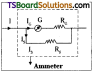
Let ‘r’ is the total resistance of ammeter, G is resistance of galvanometer and Rs is shunt connected in parallel combination of
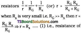
ammeter is equals to resistance of shunt.
Necessity of small shunt resistance :
Ammeter is used to measure current in a circuit. In a circuit current is constant for series combination only. So ammeter must be connected in series in a circuit. To measure the value of current exactly our ammeter must have zero resistance because in series combination (R = R1 + R2 + ………… etc) if resistance of shunt Rs is small effective resistance of ammeter is nearly equals to resistance of shunt and error in the value of current measured is also less.
![]()
Question 4.
How can a galvanometer be converted to a voltmeter? Why is the series resistance greater than the galvanometer resistance?
Answer:
A galvanometer can be converted into voltmeter by connecting a high resistance in series with galvanometer.
Conversion of galvanometer into voltmeter :
Every galvanometer has two important properties
- Resistance of galvanometer RG
- Maximum current tolerable by it say IG.
The block diagram of a voltmeter is as shown in figure.
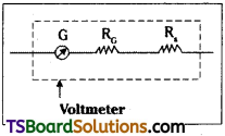
Let voltage to be measured is ‘V’.
Total resistance of voltmeter R = \(\frac{V}{I_G}\)
But from block diagram R = RG + Rs because they are in series. If Rs > > RG then resistance of voltmeter R ≅ Rs
Necessity of high series resistance :
A voltmeter is used to measure potential difference between two given points. So it must always be connected parallelly in a circuit. In parallel combination, high current will flow through low resistance. To measure potential difference exactly the voltmeter should not draw any current from circuit. Theoritically resistance of ideal voltmeter is infinity. Practically it is kept as high as possible when series resistance of volt-meter is high it draws very little current from the circuit and measurement of voltage with it is more accurate.
Question 5.
Derive an expression for the force acting between two very long parallel current-carrying conductors and hence define the ampere.
Answer:
Let two long conductors say ‘a’ and ‘b’ are carrying the currents Ia and Ib. Separation between them is say ‘d’. Conductor ‘a’ produces a magnetic field Ba at all points a long conductor b’ due to the current flowing through it.
Magnetic field due to ‘a” = Ba = \(\frac{\mu_0}{2 \pi} \frac{I_a}{d}\) ……(1)
Conductor ‘b’ carrying a current Ib is in the magnetic field produced by ‘a’. Force acting on conductor ‘b‘ due to ‘a’ is Fba = IbLBa = \(\frac{\mu_0}{2 \pi} \frac{I_aI_b}{a}\).L
Where L is length of conductor ‘b’.
Now conductor ‘a’ is in the magnetic field produced by ‘b’. Force due to ‘b’ on ‘a’ is Fab From Newton’s 3rd law Fab = – Fba
∴ Force between two parallel conductors
![]()
Force between parallel conductors per unit
If the currents in the two wires are parallel then force between them is attractive force because at the point of intersection of the two fields their directions are opposite so polarity is opposite.
Hence if currents are in same direction the conductors will attract. If currents are in opposite direction then the conductors will repel.
Definition of ampere :
From the force between two parallel conductors ampere is defined as follows.
Ampere is that value of steady current which when maintained through each conductor separated by a distance of 1 metre a part in vacuum produces a force of 2 × 10⁻⁷ newton per metre between them.
Problems
Question 1.
A current of 10A passes through two very long wires held parallel to each other and separated by a distance of lm. What is the force per unit length between them? [TS Mar. 19. 15; AF Mar. 15]
Solution:
Current i1 = i2 = 10A
Separation d = lm
Force per unit length L = lm
Force between two parallel conductors
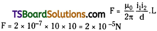
Question 2.
A moving coil galvanometer can measure a current of 10-6A. What is the resistance of the shunt required if it is to measure 1A?
Solution:
Old range i.e., maximum current to be measured i1 = 10-6 A
New range i.e., maximum current to be measured i2 = 1A
Ratio of ranges or currents to be measured,
Where G is resistance of galvanometer.
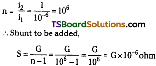
Question 3.
A circular wire loop of radius 30cm carries a current of 3.5 A. Find the magnetic field at a point on its axis 40 cm away from the centre.
Solution:
Radius of loop r = 30cm = 0.3m = 3 × 10⁻¹m.
Current i = 3.5A ; Distance of point on the axis r = 40cm = 0.4m = 4 × 10⁻¹m.
Magnetic induction field on the axis of a
Intext Question and Answer
Question 1.
A circular coil of wire consisting of 100 turns, each of radius 8.0 cm carries a current of 0.40 A. What is the magnitude of the magnetic field B at the centre of the coil? [TS May ’18]
Answer:
Number of turns on the circular coil,
n = 100 ; Radius of each turn,
r = 8.0 cm = 0.08 m ; Current I = 0.4 A
Magnitude of the magnetic field at the centre of the coil is given by the relation,
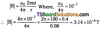
∴ Magnitude of the magnetic field
B = 3.14 × 10⁻⁴T.
![]()
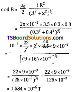
Question 2.
A long straight wire carries a current of 35 A. What is the magnitude of the field B at a point 20 cm from the wire? [TS June ’15]
Answer:
Current in the wire, 1 = 35 A ; Distance of a point from the wire, r = 20 cm = 0.2 m ; Magnitude of the magnetic field at this point is given as:
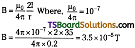
∴ Magnitude of the magnetic field at 20 cm from the wire B = 3.5 × 10⁻⁵T.
Question 3.
A long straight wire in the horizontal plane carries a current of 50 A in north to south direction. Give the magnitude and direction of Bat a point 2.5m east of the wire.
Answer:
Current in the wire, I = 50A ; ∴ Distance of the point from the wire, r = 2.5 m.
Given point is 2.5 m away from the east of the wire.
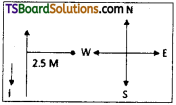
∴ Direction of magnetic field B is vertically upwards.
Note : The point is located normal to the . wire length at a distance of 2.5 m. The direction of the current in the wire is vertically downward. Hence, according to the Maxwell’s right hand thumb rule, the direction of the magnetic field at the given point is vertically upward.
Question 4.
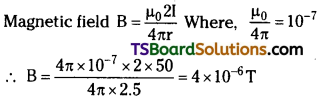
A horizontal overhead power line carries a current of 90 A in east to west direction. What is the magnitude and direction of the magnetic field due to the current 1.5 m below the line?
Answer:
Current I = 90 A; Distance of point r = 1 .5 m
Note : The current is flowing from East to West. The point is below the power line. Hence, according to Maxwell’s right hand thumb rule, the direction of the magnetic field is towards the South.
Question 5.
What is the magnitude of magnetic force per unit length on a wire carrying a current of 8 A and making an angle of 30° with the direction of a uniform magnetic field of 0.15 T?
Answer:
Current in the wire, I = 8 A ; uniform magnetic field, B = 0.15 T
Angle between the wire and magnetic field, θ = 30°;
Magnetic force per unit length f = BI sinθ
∴ f = 0.15 × 8 × 1 × sin30° = 0.6 N m-1
Question 6.
A 3.0 cm wire carrying a current of 10 A is placed inside a solenoid perpendicular to its axis. The magnetic field inside the solenoid is given to be 0.27 T. What is the magnetic force on the wire?
Answer:
Length of the wire, l = 3 cm = 0.03 m;
Current flowing in the wire, I = 10 A
Magnetic field, B = 0.27 T ; Angle between the current and magnetic field, θ = 90°
From F = BIl sinθ; F = 0.27 × 10 × 0.03 sin90°
= 8.1 × 10⁻² N
∴ Magnetic force on the wire is 8.1 × 10⁻² N.
![]()
Question 7.
Two long and parallel straight wires A and B carrying currents of 8.0 A and 5.0 A in the same direction are separated by a distance of 4.0 cm. Estimate the force on a 10 cm section of wire A.
Answer:
Current flowing in wire A, IA = 8.0 A ;
Current flowing in wire B, lB = 5.0 A
Distance between the two wires, r = 4.0 cm = 0.04 m;
Length of wire A, l = 10 cm = 0.1 m
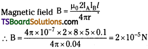
The magnitude of force is 2 × 10⁻⁵ N. This is an attractive force normal to A towards B because the direction of the currents in the wires is the same.
Question 8.
A closely wound solenoid 80 cm long has 5 layers of windings of400 turns each. The diameter of the solenoid is 1.8 cm. If the current carried is 8.0 A, estimate the magnitude of B inside the solenoid near its centre.
Answer:
Length of the solenbid, l = 80 cm = 0.8 m
There are five layers of windings of 400 turns each on the solenoid.
∴ Total number of turns on the solenoid, N = 5 × 400 = 2000
Diameter of the solenoid, D = 1.8 cm = 0.018 m ; Current in the solenoid, I = 8.0 A
Magnetic field inside the solenoid near its
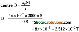
∴ Magnetic field inside the solenoid near its centre is 2.512 × 10⁻² T.
Question 9.
A square coil of side 10 cm consists of 20 turns and carries a current of 12 A. The coil is suspended vertically and the normal to the plane of the coil makes an angle of 30° with the direction of a uniform horizontal magnetic field of magnitude 0.80 T. What is the magnitude of torque experienced by the coil?
Answer:
Length of a side of the square coil, 1 = 10 cm = 0.1 m; Current in the coil, l = 12 A
Number of turns n = 20 ; Angle between plane of the coil and magnetic field, θ = 30°
Strength of magnetic field, B = 0.80 T ; But τ = n BI A sin θ
Where, A = Area of the square coil = l × l = 0.1 × 0.1 = 0.01 m²
∴ τ = 20 × 0.8 × 12 × 0.01 × sin 30° = 0.96 N m
Question 10.
Two moving coil meters, Mj and M2 have the following particulars:
R1 = 10 Ω, N1 = 30, A1 = 3.6 × 10⁻³ m², B1 = 0.25 T
R2 = 14 n, N2 = 42, A2 = 1.8 × 10⁻³ m² , B2 = 0.50 T
(The spring constants are identical for the two meters).
Determine the ratio of (a) current sensitivity and (b) voltage sensitivity of M2 and M1.
Answer:
a) Current sensitivity of M.C.G is given as:
I = NBA/k
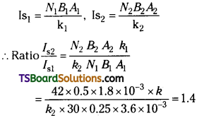
Hence, the ratio of current sensitivity of M2 to M1 is 1.4.
b) Voltage sensitivity for M.C.G is given as:
Vs2 = \(\frac{N_2B_2A_2}{k_2R_2}\)
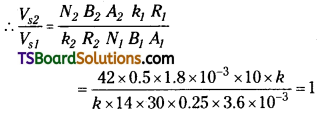
Hence, the ratio of voltage sensitivity of M2 to M1 is 1.
Question 11.
In a chamber, a uniform magnetic field of 6.5 G (1 G = 10-4 T) is maintained. An electron is shot into the field with a speed of 4.8 × 10⁶ m s-1 normal to the field. Explain why the path of the electron is a circle. Determine the radius of the circular orbit.
(e = 1.6 × 10⁻¹⁹ C,me = 9.1 × 10⁻³¹ kg)
Answer:
Magnetic field strength, B = 6.5 G = 6.5 × 10⁻⁴ ;
Speed of the electron, v = 4.8 × 10⁶ m/s
Charge on the electron, e = 1.6 × 10⁻¹⁹ C ;
Mass of the electron, mg = 9.1 × 10⁻³¹ kg
Angle between the shot electron and magnetic field, θ = 90°;
Force on electron, F = evB sin θ
This force will make the electron in circular path.
∴ Centripetal force exerted on the electron, Fc = \(\frac{mυ^2}{r}\) at equilibrium Fc = F
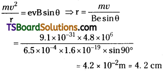
Hence, the radius of the circular orbit of the electron is 4.2 cm.
![]()
Question 12.
In exercise 11 obtain the frequency of revolution of the electron in its circular orbit. Does the answer depend on the speed of the electron? Explain.
Answer:
Magnetic field strength, B = 6.5 × 10⁻⁴ T ;
Charge of the electron, e = 1.6 × 10⁻¹⁹ C
Mass of the electron, me = 9.1 × 10⁻³¹ kg ;
Velocity of the electron, v = 4.8 × 10⁶ m/s
Radius of the orbit, r = 4.2 cm = 0.042 m ;
Frequency of revolution of the electron = υ
Angular frequency of the electron = co = 2πν
But v = rω
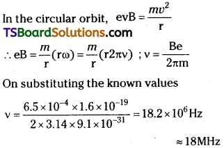
Hence, the frequency of the electron is around 18 MHz and is independent of the speed of the electron.
Question 13.
(a) A circular coil of 30 turns and radius 8.0 cm carrying a current of 6.0 A is sus-pended vertically in a uniform horizontal magnetic field of magnitude 1.0 T. The field lines make an angle of 60° with the normal of the coil. Calculate the magnitude of die counter torque that must be applied to prevent the coil from turning.
(b) Would your answer change, if the circular coil in (a) were replaced by a planar coil of some irregular shape that encloses the same area? (All other particulars are also unaltered.)
Answer:
(a) Number of turns, n = 30 ; Radius of the coil, r = 8.0 cm = 0.08 m
Area, A = πr² = π(0.08)² = 0.0201 m² ;
Current, I = 6.0 A
Magnetic field B = 1 T
Angle between the field lines and normal with the coil, θ = 60°
∴ Torque τ = n IBA sinθ …
∴ τ = 30 × 6 × 1 × 0.0201 × sin 60° = 3.133 N m
(b) Magnitude of the applied torque is not dependent on the shape of the coil. It depends on the area of the coil. So if the circular coil is replaced by a planar coil of some irregular shape of same area still then torque does not change.
Question 14.
A toroid has a core (non-ferromagnetic) of inner radius 25 cm and outer radius 26 cm, around which 3500 turns of a wire are wound. If the current in the wire is 11 A, what is the magnetic field (a) outside the toroid, (b) inside the core of the toroid, and (c) in the empty space surrounded by the toroid.
Answer:
Inner radius of the toroid, r1 = 25 cm = 0.25 m ;
Outer radius of the toroid, r2 = 26 cm = 0.26 m
Number of turns , N = 3500 ; Current in the coil, I = 11 A
(a) Magnetic field outside a toroid is zero. It is non-zero only inside the core of a toroid.
(b) Magnetic field inside the core of a toroid
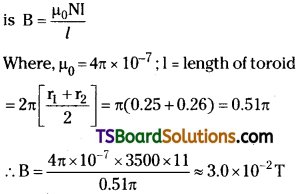
(c) Magnetic field in the empty space surrounded by the toroid is zero.
Question 15.
The wires which connect the battery of an automobile to its starting motor carry a current of 300 A (for a short time). What is the force per unit length between the wires if they are 70 cm long and 1.5 cm apart? Is the force attractive or repulsive?
Answer:
Current in both wires, I = 300 A ;
Distance between the wires, r = 1.5 cm = 0.015 m
Length of the two wires, / = 70 cm = 0.7 m
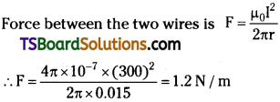
Since the direction of the current in the wires is opposite, a repulsive force exists between them.
Question 16.
A galvanometer coil has a resistance of 12 Ω and the metre shows full scale deflection for a current of 3 mA. How will you convert the metre into a voltmeter of range 0 to 18 V?
Answer:
Resistance of the galvanometer coil, G = 12 Ω
Current for which there is full scale deflection, Ig = 3 mA = 3 × 10⁻³ A
Range of the voltmeter is 0, which needs to be converted to 18 V. ∴ V = 18 V
Let a resistor of resistance R be connected in series with the galvanometer to convert it into a voltmeter. This resistance is given as:
![]()
Hence, a resistor of resistance 5988Ω is to be connected in series with the galvanometer.
![]()
Question 17.
A galvanometer coil has a resistance of 15Ω and the metre shows full scale deflection for a current of 4 mA. How will you convert the metre into an ammeter of range 0 to 6 A?
Answer:
Resistance of the galvanometer coil, G = 15 Ω Current for which the galvanometer shows full scale deflection,
Ig = 4 mA = 4 × 10⁻³ A
Range of the ammeter is 0, which needs to be converted to 6 A.; ∴ Current, I = 6 A
A shunt resistor of resistance S is to be connected in parallel with the galvanometer to convert it into an ammeter.
But shunt resistance is given by,
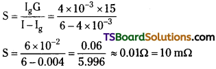
Hance, 10 mΩ shunt resistor is to be connected in parallel with the galvanometer.