Telangana TSBIE TS Inter 2nd Year Economics Study Material 1st Lesson Economic Growth and Economic Development Textbook Questions and Answers.
TS Inter 2nd Year Economics Study Material 1st Lesson Economic Growth and Economic Development
Essay Questions
Question 1.
Explain the concepts of economic growth and economic development. What are their differences?
Answer:
In common parlance the two terms – economic growth and economic development connote the same meaning and there appears to be no difference between them. Generally, economic growth refers to the problems of developed countries and economic development to those of under developed countries. But some economists have drawn a line of demarcation between economic growth and economic development.
Economic growth :
According to C.R Kindleberger, “Economic growth means more out-put, while economic development implies both more output and changes in the technical and institutional arrangement by which it is produced and distributed”. The word growth is primanly of quantitative significance, while the word development is of both quantitative and qualitative significance.
Economic Development :
‘Economic development’ is a wider concept than the concept of ‘economic growth’. Development includes not only economic growth but also certain other positive changes in other spheres of life. In fact, it includes development in all spheres. Economic development is closely associated with the concept of economic growth. It implies progressive changes in the socioeconomic structure of a country, where a sustained rise in livihg standards as well as an equitable growth to be achieved.
Economic growth is a necessary but not sufficient condition of economic development. Economic development is a normative concept. The definition of economic development given by Michael R Todaro is an increase in living standards, improvement in self-esteem needs and freedom from oppression as well as a greater choice.
According to United Nations Expert Committee, “Development concerns with not only man’s material needs but also the improvement of the social conditions of his life. Development is, therefore not only economic growth, but also growth plus change – social, cultural, institutional and economic.
According to Michael P. Todaro “Development must be conceived as a multidimensional process involving major changes in social structures, popular attitudes and national institutions as well as the acceleration of economic growth, the reduction of inequality and the eradication of poverty”. John Friedmann defines development as “an innovative process leading to the structural transformation of social system”.

Question 2.
Explain the objectives of economic development.
Answer:
The major objectives of economic development countries like India can be mentioned as here under :
1. High Rate of Growth :
All the developing economies including countries such as China and India are striving hard to achieve high rates of economic growth. For instance all the Indian Five Year plans have given primary importance to higher growth of real national income. During the first three decades of planning, the rate of economic growth was not so encouraging in our economy. Till 1980, the average annual growth arate of Gross Domestic Product was 3.75 per cent jagainst the average annual growth rate of pooplation at 2.5 percent. Hence the per capita income grew only around 1 per cent. But from the 6th plan onwards, there has been considerable change in the Indian economy.
In the Sixth, Seventh and Eighth plans the growth ratge was 5.4 per cent, 5.8 per cent and 6.8 per cent respectively. The Ninth Plan, started in 1997 targeted a growth rate of 7 per cent per annum and realized only 5.35 per cent average GDP growth. In the later years, the economy achieved even a high rate of growth of 9 per cent. Though this is considered to be a relatively high rate of growth, China achieved even 10 per cent rate of economic growth in first decade of 21st century. For the Twelfth plan (2012-17) target Us 7.9 per cent average growth. From 2014-15 to 2018-19, GDP has grown at 7.5 per cent.
2. Economic Self-Reliance:
Self reliance means to stand on one’s own. legs. In the Indian economic context, it implies that dependence on foreign aid should be as minimum as possible. At the beginning of planning, we had to import food grains from USA to meet our domestic demand. Similarly, for accelerating the process of industrialization we had to import capital goods in the form of heavy machinery and technical know – how. For improving infrastructural facilities like roads, railways, power, the country had to depend on foreign aid to raise the rate of investment.
As excessive dependence on foreign sector may lead to economic colonialism and in this regard the planners rightly mentioned the objective of self – reliance from the Third Plan onwards. In the Fourth Plan much emphasis was given to self-reliance, particularly in the production of food grains. In the Fifth Plan, our objective was to earn sufficient foreign ex-change through export promotion and import substitution. India has made remarkable progress in achieving self-reliance. In later years, most of the developing economies such as China, Brazil, South Africa, South Korea, Vietnam and some of the other African, Asian and Latin American countries are aiming to achieve self-reliance.
3. Social Justice :
Social justice means equitable distribution of the wealth and income of the country among different sections of the society. In India, we find that a large number of people are poor, while a few lead a luxurious life. Therefore, another objective of development is to ensure economic and social justice and to take care of the poor and weaker sections of the society. The five year plans in India have highlighted four aspects of social justice. They are :
i) Adherence to democratic principles in the political structure of the country.
ii) Establishment of social and economic equity and removal of regional disparities;
iii) Putting an end to the process of centralization of economic power and simultaneously attaining decentralization of power; and
iv) Efforts to raise the conditions of backward and depressejd classes.
4. Modernization :
Modernization aims at improving the standard of living of thepeople by adopting a better scientific technique of production, by replacing the traditional backward methods and by bringing changes in the rural structure and institutions. These changes aim at increasing the share of industrial output in the national income, upgrading the quality of products and diversifying the Indian industries. Further, it also includes expansion of banking and non-banking financial institutions to agriculture and industry. It envisages modernization of agriculture including implementation of land reforms. Currently modernization is taking place due to phenomenal growth of information technology sector. Land reforms either of radical nature or modest nature have been implemented in most of the developing countries, especially in countries like China, Vietnam and India.
5. Economic Stability :
Economic stability is ensured wh£n a non-inflationary full employment growth occurs in a country. After the Second Plan, the price level started increasing in India for a long period of time. Therefore, the planners have tried to stabilize the economy by properly controlling the rising trend of the price level. The progress in this direction has been satisfactory. Broad objective of economic development has been a non-inflationary self- reliant growth with social justice.
6. Sustainable Development :
The Brundtland Report defined sustainable development as “meeting the needs of the present generation without compromising the needs of future generations”. Sustainable development means that development should ‘keep going’.
Sustainable development aims at accelerating economic development in order to conserve and enhance the stock of environmental, human and physical capital without making future generations worse off. The damaging effects of economic development on environmental degradation can be reduced by a judicious choice of economic and environmental policies and environmental investments. Choice between policies and investments should aim at harmonising economic development with sustainable development.
7. Inclusive Growth :
The inclusive growth as a strategy of economic development received attention owing to a rising concern that the benefits of economic growth have not been equitably shared. The inclusive growth stresses the inclusiveness of the hitherto excluded population in the growth process, which is expected to bring in several other benefits as well to the economy. The concept of inclusion should be seen as a process of including the excluded marginalized sections of the population whose share in the total income remained relatively at a low level, for instance bottom 20% of the population getting a share of 2 to 3% of the national income. Hence, by adopting inclusive growth strategy, if the bottom 20% share can increase to 5-10% at least, then it can be termed as inclusive growth.
Question 3.
Explain the Indicators of economic development.
Answer:
The Economic Development Indecators are ae follows .
1. Real National Income :
One of the methods to measure economic development is in terms of an increase in the economy’s real national income over a long period of time. Higher real national income is the index of higher level of economic development and vice-versa. The division of global economy into developed and developing countries is based on the real national income. This is not a satisfactory indicator due to the following reasons : (a) The price changes have to be ruled out while calculating real national income.
But variations in prices are inevitable. A short period rise in national income does not constitute economic developnjent. (b) It fails to take into consideration changes in the growth of population. If a rise in real national income is accompanied by a faster growth in population, there will be no economic development but retardation, (c) It does not reveal the social costs to society, (d) It explains nothing about the distribution of income in the economy, (e) There are certain conceptual difficulties in the measurement of GNP.
2. GNP Per Capita :
Some economists have taken per capita real income as an economic development indicator on the basis of the increase in per capita real income of the economy over a long period. The increase in per capita real income of any’country shows an increase in economic growth rate of the country rather than economic development. Economic development includes changes in many spheres besides a rise in per capita real income. This indicator emphasizes that for economic development, the rate of increase in real per capita income should be higher than the growth rate of population.
3. Welfare :
Other indicator of economic development is econqmic welfare. Economic development is regarded as a process whereby there is an increase in the consumption of goods and services of individuals. According to Okun and Richardson, economic development is “a sustained, secular improvement in material well-being, which we may consider to be reflected in an increasing flow of goods and services”.
4. Social Indicators or Basic Needs :
Certain economists have tried to measure economic development in terms of social indicators. Social indicators are referred to as the basic needs for development. Basic needs focus on alleviation of poverty by providing basic human needs to the poor. The direct provision of basic needs such as health, education, food, water, sanitation and housing affects poverty in a shorter period and with fewer monetary resources than GNP/GNP per capita strategy. Basic needs lead to a higher level of productivity and income through human development in the form of educated and healthy people.
Norman L.Hicks and Paul P.Streeten consider six social indicators for basic needs.
| Basic Needs | Indicators |
| 1. Health | Life expectancy at birth |
| 2. Education | Literacy signifying primary school enrolment as percent of population |
| 3. Food | Calorie supply per head |
| 4. Water supply | Infant mortality and percentage of . population with access to portable water. |
| 5. Sanitation | Infant mortality and percentage of population with access to sanitation. |
| 6. Housing | None |
5. Physical Quality of Life Index (PQLI) :
It was invented by M.D. Morris in 1979. He constructed a composite Physical Quality of Life Index relating to 23 countries for a comparative study. This is a non-income indicator of economic development because this uses physical quality of life as ah indicator. This method of measuring economic development is based on the following three things. They are: (i) life expectancy, (ii) infant mortality rate, and (iii) basic literacy. This index mesures performance in meeting the most basic needs of people. This index represents basic needs such as health, education, drinking water, nutrition and sanitation.
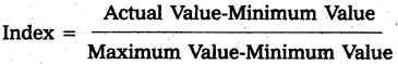
6. Human Development Index (HDI) :
Mahbub-Ul-Haq developed the Human Devel-opment Index and UNDP incorporated it in its first Human Development Report in 1990. Since then, the UNDP is presenting the measurement of human development in its annual report.
Human Development Index (HDI) is a modem indicator of economic development. It is a statistical tool used to measure a country’s overall achievement in its social and economic dimensions. The following indicators are required to construct HDI:
- Life expectancy at birth.
- Education – adult literacy, combined gross enrolment ratio.
- Real GDP per capita based on purchasing power parity in terms of dollar.
For the construction of HDI, an index is created for each of these indicators with fixed minimum and maximum values for each of these indicators as shown below :
- Life expectancy at birth, 25 years and 85 years.
- Adult literacy rate, 0% and 100%.
- Combined gross enrolment ratio, 0% and 100%
- Real GDP per capita (PPP) $100 and $40,000.
India’s HDI value is shown in the following table :
| Year | HDI Value |
| 1990 | 0.427@ |
| 1995 | 0.546 |
| 2001 | 0.472 |
| 2002 | 0.595 |
| 2007 | 0.612 |
| 2010 | 0.519 |
| 2013 | 0.586 |
| 2017 | 0.640 @ |
| 2018 | 0.647 β |
7. Gender related Development Index (GDI) :
The HDR, 1995 introduced two global gender indices. These are Gender related Development Index (GDI) and Gender Empowerment Measure (GEM). The GDI is a composite, index which measures the average achievement of population in the same dimensions as the HDI while adjusting for gender inequalities in the level of achievement in the three basic aspects of human development. It uses same variables as the HDI, disaggregated by gender.
The greater the gender inequality in human development, the lower the GDI compared to HDI. The greater the difference between HDI and GDI, the more is the inequality. There is a greater awareness in the world about gender inequality and efforts are being made to reduce gender inequality. Women movements are promoting and working for gender equality.
8. The Social Progress Index (SPI) :
The SPI measures the extent to which a country provides for the social and environmental needs of their citizens. Fifty four indicators in the areas of basic human needs, foundations of well-being, and opportunity to progress show the relative performance of nations. The index is published by the non-profit Social Progress Imperative, and is based on the writings of Amartya Sen, Douglass North, and Joseph Stiglit2. The SPI measures the well-being of a society by observing social and environmental outcomes directly rather than the economic factors. The social and environmental factors include wellness, equality, inclusion, sustainability and personal freedom and safety.
9. Multi – dimensional Poverty Index (MPI) :
First introduced in 2010, it is an attempt designed to illustrate the many deprivations faced by the mpst severely disadvantaged. The MPI requires a household to be deprived in multiple indicators at the same time. A person is multi-dimensionally poor if the weighed indicators in which he or she is deprived add up to at least 33 per cent. The MPI is closely linked to the Millennium Development Goals and includes ten components.
- Possession of some assets,
- Nutrition
- Child morality
- Access to drinking water,
- Access to sanitation
- Access to a safe room,
- Access to electricity
- Access to an improved cooking oil,
- Years of schooling
- Children enrolled in school
10. Economic Growth :
It measures the annual increase in GDP, GNP and GDP per Capita or GNP per capita.
11. Gross National Happiness Index :
Countries like Bhutan are measuring their development with gross national happiness index. Hence, there is a need to bring a change in the existing method of measuring the development.
Question 4.
Explain the factors hindering economic development.
Answer:
1. Inadequate Natural Resources :
Developing countries are too populous. As such, serious shortage of land is a common phenomenon, which leads to many damaging effects. With lesser lands, there will be significant fall in cultivation activities, which are the main source of income in poor countries. This is being made worse with low level of technology, which could have helped them to produce on a mass scale.
a) Untapped Resources :
Many poor countries (Sub Saharan African) are blessed with natural resources. However, most of them are untapped. The reason is lack of research and development which may lead to low discovery of mineral deposits.
b) Inefficiently Managed Resources :
Many poor countries do not achieve both productive and allocative efficiency. Productive inefficiency exists due to absence of competition, contracts and projects are awarded to family members or to the persons having political patronage and government adopting a closed economy policy. Someone else can still be made better off without making someone else worse off. But globalization had changed the pattern of utilization of economic resources, where competition is encouraged and resources are flowing into the fields which are being efficiently managed.
2. Lower Rate of Growth of Human Capital :
Developing countries have low allocation of budget on education and health sector. Low spending on education means many will be unskilled. Lesser availability of healthcare means lower life expectancy, more days taken off as leave resulting in lower output and loss of workforce at productive age. In this regard Amartya Sen’s entitlements approach is noteworthy where education acquires a considerable amount of importance as a causative factor for capabilities of individuals where they can qualitatively contribute to development of the nation. Since LDCs have a dearth of critical skills and knowledge, physical capital cannot be utilised productively.
3. Lack of Infrastructure :
Due to many reasons, infrastructure development is far left behind. Nothing much has been done to improve the facilities like power, credit, telecommunications and transportation, which are key Services that will attract investment. Roads, bridges, harbours and railways are in less desirable condition and may adversely affect the timely delivery of goods.
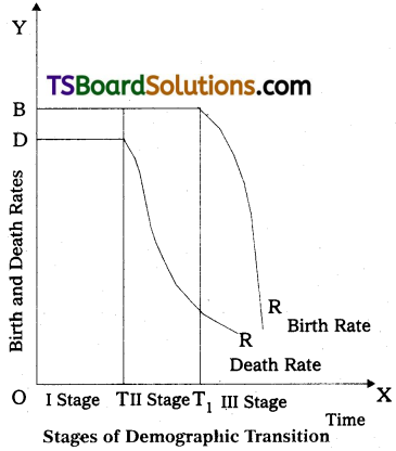
1.4.4 Vicious Circles of Poverty :
Since an underdeveloped economy lacks the proper and modem means of economic development, its economic development becomes an uphill task. This situation can be summed up as “a country is poor because it is poor”.
The basic vicious circle stems from the fact that in developing countries total productivity is low due to deficiency of capital, market imperfections, economic backwardness and underdevelopment. The vicious circles operate both on the demand side and the supply side. The demand side of the vicious circle is that the low level of real income leads to a low level of demand which leads to a low rate of investment and hence back to deficiency of capital, low productivity and low income.
The following figure shows the supply side of the vicious circle is that the low pro-ductivity is reflected in low real income. This means low savings which lead to low invstment and to deficiency of capital. This leads to low level of productivity arid back to low income.
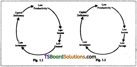
With structural changes, the vicious circles in many developing countries can be avoided and even some of the newly liberated African Countries are slowly heading in the growth path.
5. Low Rate of Capital Formation :
In LDCs the masses are poor, mostly illiterate and unskilled, use outdated equipment and production methods. Their marginal productivity is low which leads to low real income, low saving, low investment and to a low rate of capital formation. Small sums which they may be able to save are often hoarded or used in purchasing gold etc. Most of the savings are only from the high income group and these do not flow into productive channels due to their conspicuous consumption.
6. Socio – Cultural Constraints :
Social institutions and attitudes, traditional beliefs and values, rigid stratification of occupations, motives to save and invest, money spent to meet social obligations, nepotism, inefficient and bad administration, bribery, social attitude towards education, prejudice against manual work, oriental religions, high value for leisure and blind force of fate etc. are not conductive to economic development. These inhibit the progress in underdeveloped countries.
7. Agricultural Constraint :
The environment in which farmers operate the technology available to them, the incentives for production and investment, the availability and prices of input?, the provision of irrigation, the climate and the prices of agricultural products are the areas in which the constraints are to be foun.
8. Foreign Exchange Constraint :
Due to certain disequalising forces in the world economy, the gains from trade have gone to the developed countries and as a result foreign exchange constraint has taken place. There has been phenomenal rise in the exports of urn derdeveloped countries. But this has not contributed much to the development, as the export sector has developed by neglecting other sectors of the economy. Too much dependence on exports has exposed these developing countries to international fluctuations in the demand for and prices of their products. An improvement in their terms of trade is not accompanied by an increase in output and employment due to market imperfections, inadequate overhead capital and structural maladjustments.
Question 5.
Explain the factors promoting economic development.
Answer:
Factors Promoting Economic Development :
There are mainly two types of factors which influence the economic development of a country. They are
I. Economic Factors :
Economists regard factors of production as the main economic factors that determine growth or development. The growth rate of the economy rises or falls as a consequence of changes in them. These economic factors are discussed below.
1. Capital Formation :
When the capital stock increases with the passage of time, this is called capital formation. The strategic role of capital in raising the level of production has been acknowledged. The country which wants to accelerate the pace of growth has no choice but to save a high ratio of its income, with the objective of raising the level of investment unless otherwise it can attract foreign investment on a large scale.
Whatever be the economic system, a country cannot hope to achieve economic progress unless a certain minimum rate of capital accumulation is realized. The incremental capital- output ratio (ICOR), which refers to the additional amount of capital required to produce an additional unit of output, assumes greater importance in economic growth.
2. Natural Resources :
The principal factor affecting the development of an economy is the natural resources or land. In economics land includes the land area and the quality of the soil, forest wealth, minerals and oil resources, good climate and eco system, water and seta resources etc. For economic growth, the existence of natural resources in abundance is essential. A country which is deficient in natural resources may not be in a position to develop rapidly. In fact, natural resources are a necessary condition for economic growth but not a sufficient one. Japan and India are the two contradictory examples.
3. Agrarian Structure :
The agrarian system, where ownership of land becomes important besides the method of cultivation as they play an important role in bringing about economic development. Land reforms and modernization of agriculture through technological changes, improved inputs, marketing and credit are important for a faster agricultural growth of the economy.
4. Markatable Surplus of Agriculture :
The term ‘marketable surplus’ refers to the excess of output in the agricultural sector over and above what is required to allow the rural population to subsist. However, the marketed surplus is an indicator of progress in agriculture sector.
The importance of the marketable surplus in a developing economy emanates from the fact that the urban industrial population subsists on it. With the development of an economy, the ratio Of the urban population increases. As a result demand increases for food grains. This demand must be met adequately; otherwise, the consequent scarcity of food in urban areas will arrest the economic growth.
5. Industrial Structure :
The industrial structure demands the relative importance of large scale, small scale and cottage industries and the level of technology being used in these industries. A change in the structure where modernization takes place due to adoption of recent technological advances will lead to a higher tempo of economic development in the developing economies.
6. Structural Changes :
Structural changes imply the transition from a traditional agricultural society to a modem industrial society involving a radical transformation of existing institutions, social attitudes and motivations. These changes lead to increasing employment opportunities, higher labour productivity, the stock.of capital, exploitation of new resources and improvement in technology.
7. Organisation :
It is an important aspect of the growth process. It relates to the optimum use of factors of production in the economic activities. The entrepreneur is performing the task of an organiser and undertaking risks and uncertainties in the business. But less developed countries lack in entrepreneurial activity and less developed countries should create a climate for encouraging entrepreneurship. For this, the provision of all the required social, economic and technological institutions is necessary.
8. Technological Progress: Technological changes are related to changes in the production methods which are the result of new innovations. Changes in technology lead to increase in the productivity of labour, capital and other production factors. Schumpeter and Kuznets regarded innovation as the most important technological factor in economic growth. The spending of high percentage of national income on Research and Development is required.
9. Division of Labour :
Adam Smith gave much importance to the division of labour in economic development. But division of labour depends upon the size of the market. When the scale of production is large there is greater specialisation and division of labour. The growth prodess in less developed countries can be accelerated by widening of the market through adoption of modem means of transport and communications.
10. Foreign Trade :
Foreign trade has proved to be beneficial to countries, which have been able to set-up industries in a relatively short period. These countries like Japan and South Korea eventually captured international markets for their industrial products. Therefore, a developing country should not only tiy to become self-reliant in capital equipment and other industrial products as early as possible, but it should also push the development of its industries to such economy and yet face no difficulty in making economic progress. In today’s entirely different world situation, a country would find it difficult to grow along this path of development.
II. Non – Economic Factors :
It is obvious that non-economic factors are also equally important in development as economic factors. Let us tiy to understand how they influence the process of economic development:
1. Human Resources :
Human resources are considered as very important factor in economic development. Human being provides labour power for production and if in a country’s labour is efficient and skilled, its capacity to contribute to growth will be high. The productivity of illiterate, irrational, unskilled, disease ridden, superstitious people is generally low and they do not provide much to development in a country. In case either human resources remain unutilized or the labour management remains defective, it will be a burden on the economy.
Efficiency or Productivity of labour force depends upon health, education and social services. The level of technical expertise has a direct bearing on the development. As the scientific and technological knowledge advances, man discovers more sophisticated techniques of production which steadily raise the productivity levels.
2. Political and Administrative Factors :
Dadabhai Naoroji has also explained in his classic work ‘Poverty and Un British Rule in India’ that the drain of wealth and capital from India under the British rule -/as the major cause for absence of development in India during that period.
‘Political and administrative factors also helped in modem economic growth. The eco- npmic growth of Britain, Germany, the United States, Japan and France is due to their.politi- cal stability and strong administration. But, Italy has not been able to grow upto their level due to political instability and corrupt and weak administration. Peace, protection and stability have encouraged the development of entrepreneurship in developed countries, along with the adoption of appropriate monetary and fiscal policies.
3. Social Factors :
Social attitudes, values and institutions also influence economic growth. Attitudes are beliefs and values that cause human behaviour to be “What it is”. Values refer to motivations of human behaviour towards particular ends. Myrdal advocates the adoption of modernization values for the rapid economic development of less developed countries.
Changes in attitudes due to modernization of values lead to development of the agricultural, industrial and tertiary sectors of the economy. , But the development of these sectors is hot possible without, entrepreneurship. According to Myrdal, less developed countries lack entrepreneurship because they are deficient in persons with right attitude for entrepreneurship.
Mass participation in development programmes is a pre-condition for accelerating the growth process. However, people show interest in the development activity only when they feel that the fruits of growth will be fairly distributed. Experiences from a number of countries suggest that whenever the defective social system allows some elite groups to appropriate the benefits of growth, the general mass of people develop apathy towards State’s development programs. Under those circumstances, it is futile to hope that masses will participate in the development projects undertaken by the State. India’s experience during the whole period of development planning is an example.
Question 6.
Discuss the characteristics of Developed Countries.
Answer:
Characteristics of Developed Economies
Based on their GNI per capita, countries are classified as low income, middle income and high income countries. Income classifications are set each year on July 1. These official analytical classifications are fixed during the World Bank’s fiscal year (ending on June 30). According to World Bank Report (2014) entitled “Risk and Opportunity Managing Risk for Development”, the world economies have been divided into four types based on per capita GNI $ (dollar) value i.e.,
- Low Income Economy – US$ 1035 or less than it
- Low Middle Income Economy – US$1036 – US$4085
- Upper Middle Income Economy – US$4086 – US$12615
- High Income Economy – US$12616 and more
A developed economy is characterized by an increase in capital resources, improvement in efficiency of labour, better organization of production in all spheres, development of means of transport and communication, growth of banks and other financial institutions, urbanization and a rise in the level of living, improvement in the standards of education and expectation of life, greater leisure and more recreation facilities and the widening of the mental horizon of the people and so on. In short, economic development must break the poverty barrier or the vicious circle and bring into being a self-generating economy so that economic growth becomes self-sustained.
The main characteristics of developed countries are as follows :
1. Significance of Services and Industrial Sector :
Most of the developed countries have given much .importance to the development of industrial sector. They have large capacities to utilize all resources of production, to maximize national income and to provide employment for the jobless people. As per the sectoral contribution to GDP these countries receive the major portion of their GDP from the non-agriculture sectors which include industry and services. For instance, in 2014 the U.K. received 79.6 per cent of her GDP from the services, 19.8 per cent from the industry and 0.6 per cent from agriculture. The same is the case with the U.S.A., Japan and other west European countries.:
Similarly, coming to employment, in 2011 just 1 per cent of employment was in agriculture in the U.K. and this was 47 per cent in Indian agriculture.
2. High Rate of Capital Formation :
Developed countries are generally very rich as they maintain a high level of savings and investment, with the result that they have huge amount of capital stocks. Gross capital formation will be more in these developed countries. Well-developed capital markets, high level of savings, broader business prospects as well as innovative entrepreneurship have led to a high growth of capital formation in these economies. Such a situation can be observed with the help of following table :
| Country | 1990 | 2018 |
| USA | 18 | 21 |
| UK | 20 | 17 |
| GERMANY | 24 | 22 |
| JAPAN | 33 | 24 |
| CHINA | 35 | 44 |
A higher rate of gross capital formation alone can pave the way for economic development.
3. Use of Modern Production Techniques and Skills :
The new and advanced techniques have been used for the exploitation of the physical human resources. These countries have, therefore, been giving priority to the scientific research so as to improve and evolve the new techniques of production. Consequently, these countries find themselves able to produce goods and services of a better quality at a comparatively lesser cost. It is because of the use of modem and mass production techniques and latest skills, that the countries like Japan, Germany and Israel could have developed their economies very rapidly, though they have limited natural resources. This was shown in the following table
Expenditure on R & D
| Country | Expenditure on R & D as % of GDP 2017 |
| USA | 2.80 |
| UK | 1.67 |
| SWITZERLAND | 3.37 (2015) |
| GERMANY | 3.04 |
| JAPAN | 3.20 |
| INDIA | 0.62 (2015) |
| CHINA | 2.1 |
It is clear that the Switzerland spent 3.37 per cent of its GDP on Research & Development (R & D) during 2015, whereas India spent only 0.62 per cent of its GDP on R & D in 2015.
4. Low Growth of Population :
The developed countries, like the U.S.A., the U.K. and other western European countries have low growth of population because they have low level of birth rate followed by low level of death rate. Good health conditions, high degree of education and higher level of consumption of the people have led to maintain low growth of population. The life expectancy in these countries is also very high. The average annual growth rate of population in developed countries is 0.7 percent as compared with 2 percent in developing countries.
Average life expectancy at birth is 75 years in the developed countries whereas in the developing countries it is 51 years. Besides this, the entire society, its structure and values are found to be more conductive to the goal of rapid industrial and economic development. Further, dignity of labour is maintained. The economic motive and strong desire to lead a better social life always inspire people to contribute greatly to the process of development.
5. Higher Per Capita Gross National Income in $ (Purchasing Power Parity) :
One of the important features of the developed economies is the higher per capita national income, which can be seen from the table given below.
Per Capita Gross National Income at Market Prices (In US Dollars), 2018
| Country | Per capita GNI
Purchasing Power Parity Basis |
| USA | 63,690 |
| UK | 45,350 |
| SWITZERLAND | 68,820 |
| GERMANY | 54,650 |
| JAPAN | 44,380 |
| CHINA | 18,170 |
| INDIA | 7,680 |
It is evident from the above table that the per capita GNI of USA in the year 2018 was US $ 63,690, UK was $ 45,350 and Switzerland $68,820, whereas India’s GNI was $7,680. It indi-cates that the developed countries are endowed with higher per capita GNI. It may be noted that in 2018 the average per capita GNI of USA at the purchasing power parity rates was 8.3 times that of India.
Question 7.
Analyse critically the characteristics of developing economics with special reference to India.
Answer:
Characteristics of Developing Economies with Special Reference to India :
The major characteristics of developing economies in general and the Indian economy in particular are as follows :
1. Low Per Capita Income :
According to Caimcross, “the underdeveloped countries are the slums of the world economy”.
The per capita NNP in India in 1995-96 was about Rs. 9,300 and in 2012-13 it was Rs. 22,000. It is one of the lowest in the world. Among the 133 countries of the world, India’s rank is 110. The per.capita GNI of an Indian in 2018 was $ 7680 at the purchasing power parity v rates. In the same year the average per capita GNI of USA is 8.3 times that of India. Whatever progress has been made in terms of the increase in production since independence, the same is not reflected in increase in per capita income because of rapid growth of population along with the growth of production.
This means that a large proportion of population have income level much below the average. For instance, according to the Rangarajan Committee’s estimates, 29.5 percent of total population in 2011-12 were living below the poverty line i.e. they are not able to afford even the minimum nutrition required. Due to the low level of living, the efficiency of labour is also low.
2. Predominance of Agriculture :
In developing countries two-thirds or more of the people live in rural areas and their main occupation is agriculture. Agriculture is mostly unproductive.
In India, 42.7 per cent of the working population was engaged in agriculture in 2017 and its contribution to the gross value added (GVA) is 16.5 percent in 2019-20 (Economic Survey, 2019-20). Rainfall is the main source of irrigation. The technology used in agriculture is traditional in nature and modernization is slowly taking place. Although in some areas modem techniques of cultivation are in application, still the vast agricultural area uses primitive techniques of cultivation. A’ vast area of agricultural land is still not covered by irrigational facilities. Agriculture continues to be a depressed industry as the productivity per person engaged in it is very low.
3. Capital Deficiency :
Developing countries are characterized as “capital-poor or low- saving and low investing” economies.
The low level of income results in low level of savings, which results in low level of capital formation. For want of capital, other resources like labour and natural resources remain unutilized. India has a large potential for renewable as well as non-renewable resources. The country is not able to utilize them fully for want of capital. As per Annual Report of RBI 2019, in 2017-18, gross domestic saving (GDS) rate is 30.1 percent and gross domestic investment (GDI) rate is 32.3 per cent at current prices.
4. Technological Backwardness :
Deficiency of capital hinders the process of scrapping off the old techniques and the installation of modem techniques. Illiteracy and absence of a skilled labour force are the other major hurdles in the spread of techniques in the backward economy. The technological backwardness is not only the cause of economic backwardness, but also the result of it.
In large parts of almost all sectors of the Indian economy, technology used in production is backward.. The expenditure incurred on research and development is low. Advanced technology is in use in a few industries only. With the liberalisation of the economy, new technology is being adopted by a large number of enterprises for their survival.
5. Inadequate Infrastructure Facilities :
Infrastructural facilities include banking, education, public health, drinking water, drainage, irrigation, power, transport and communications. These facilities are essential for the development of agriculture, industrial and services sectors. All these facilities are inadequate.
6. Demographic Features :
The average annual growth rate of population in developing countries is 2 percent as compared with about 0.7 percent in developed countries. The percentage of population under 15 years of age is about 40 in developing countries, compared with only 20 to 25 percent iii developed countries. Average life expectancy at birth is roughly 51 years in developing countries whereas in the developed countries it is 75 years. It is 68.5 years in India as per 2011 census. As per HD report 2019, it is 69.4 years in 2018.
The density of population in India in 2006 was 373 per sq.km as compared with 33 in USA and 141 in China. The number of deaths of infants of less than one year of age per thousand live births in India was 44 in 2010. This shows the inadequate medical facilities, low level of nutrition and poor sanitary conditions.
India’s population is very large, it is 129.5 crores in 2014, and it is rising at a rate of 1.64 per cent (2011) per annum.
7. High Rate of Illiteracy :
Most of the underdeveloped countries suffer from mass illiteracy. Illiteracy retards development. A minimum level of education is necessary to acT quire skills. India ranked at the 129th positon in 2018 on the basis of the Human Development Index which is based on life expectancy, adult literacy, combined enrolment ratio, an?l real GDP per capita in US Dollars.
Illiteracy rate in females is much higher than in males. In India as per 2011 census literacy rate, male literacy rate and female literacy rate (percent) are 74.0, 82.14 and 65.5 respectively.
8. A Dualistic Economy :
Almost all developing containing have a dualist economy.
Dualism is also characterised by the existence of an advanced industrial system and an indigenous backward agricultural system. The industrial sector uses capital intensive techniques and produces a variety of capital goods and durable consumer goods. The rural sector with traditional techniques is producing agricultural commodities. There is also financial dualism consisting of the unorganised money market with very high interest rates on loans and the organised money market with low interest rates and abundant credit facilities.
9. Underdeveloped Natural Resources :
Underdeveloped countries have not been suc-cessful in over coming the scarcity of natural resources by appropriate changes in technology and social and economic organization. The natural resources are underdeveloped due to various inhibitions such as their inaccessibility, lack of technical knowledge, non availability of capital and the small extent of the market.
10. Lack of Entrepreneurship :
Another feature of underdeveloped countries is the lack of entrepreneurial ability. Entrepreneurship is inhibited by the social system which denies opportunities of creative faculties. The small size of the market, lack of capital* lack of infrastructural facilities, technological backwardness, absence of private property, absence of freedom of contract and law and order hamper enterprise and initiative.
11. Unemployment and Disguised Unemployment :
In underdeveloped countries there is vast open unemployment and disguised unemployment. The unemployment is spreading with urbanisation and the spread of education. But the industrial sector has failed to expand along with the growth of labour force. In India unemployment is structural and is the result of a deficiency of capital. In under developed countries under employment or disguised or concealed unemployment is a notable feature. In Indian agricultural sector, a much larger number of labourers are engaged than are really needed. The marginal product of labour in agriculture is negligible or it may be zero or may be negative.
The Eleventh Plan (2007-12) has a backlog of 37 million unemployed and estimated that 45 million are likely to be the new entrants to the labour force during this plan. Unemployment reached to 6.1 percent in 2017-18. Thus, the provision of employment becomes a major task of the planning process in India.
12. Social Institutions s In developing countries social institutions are not conducive to economic development. The Indian society is divided into many castes and sub-castes resulting in frictions in the society. The religious and social beliefs and customs to certain extent inhibit the development of scientific attitudes. People are conservative and superstitious and governed by customs and traditions. Joint family system and the caste system obstruct mobility Of labour.
13. Foreign Trade Orientation :
Underdeveloped economies are generally foreign trade oriented. These countries export primary products and import consumer goods and machinery. This too much dependence on exports of primary products leads to serious repercussions in their economies in the forms of neglecting other sectors, susceptible to international fluctuations. Developing countries are facing with the balance of payments difficulties. In India the recent rapid increase in the import bill together with stagnating exports has led to a significant worsening of the trade balance (US $ – 180.3 billions in 2018-19).
Short Answer Questions
Question 1.
Define economic growth and write its essential aspects.
Answer:
Economic growth is a narrower concept than economic development. It is an increase in a country’s real national output which can be caused by an increase in the quality of resources. Economic growth can be measured by an increase in a country’s gross domestic product (GDP).
According to Michael P. Todaro, “Economic growth is a steady process by which the productive capacity of the economy is increased over a time to bring about rising levels of national output and income”.
According to Simon Kuznets, “Economic growth may be defined as a long term process where in the substantial and sustained rise in real national income, total population and real per capita income takes place”.
According to Maddison, “The raising of income levels is generally called economic growth in rich countries and in poor ones it is called economic development”.
John Friedmann defines growth as an expansion of the system in one or more dimensions without a change in its structure.
Essentials of Economic Growth
From the above stated definitions, the essential features of economic growth can be explained as given here under:
- Economic growth shows a higher rate of increase in real per capita income than the rate of growth of population.
- Economic growth is always linked with a large increase in productive ability of the economy.
In short-run, economic growth is measured with the help of rate of saving and capital- output ratio, while in the long run it is measured with the help of increase in labour force and technological growth. Thus the four determinants of economic growth can be understood as (a) rate of saving of the economy; (b) capital-output ratio, where the stock of capital is divided by output; (c) rate of growth of labour force and (d) rate of growth of technological progress.
Question 2.
Explain the structural changes in economic development.
Answer:
Economic development represents structural changes in various sectors of the country: There will be a change in the occupational structure. In economic development there will be a decrease in the share of labour force in primary sector and an increase in the shares of labour force in secondary sector and tertiary sector. The structural changes can be seen as follows :
1. There will be a change in the structure of national output. The contribution of primary sector in the national output falls and the shares of secondary and tertiary sectors slowly go up.
2. There will be a change in the structure of industrial production. There will be an increase in the production of capital goods vis-a-vis the production of consumer goods.
3. There will be a change in the structure of foreign trade. The share of primary goods in exports decreases and the share of capital goods in imports increases. Accordingly, in economic development there will be an increase in exports of manufactured and final goods as well as services. Similarly, there will be a decrease in the imports of consumer items. In present context of globalization, the developing countries are also actively participating in world agricultural trade, where agricultural exports are being given importance, besides limiting the importation of consumer items. But this cannot be considered as a reversal of the earlier trend in all the developing countries.
4. There will be a change in the structure of technology. In economic development, modem and advanced techniques of production’are used in all the sectors of economy.
5. There will be a change in the social and institutional sectors. Due to economic devel-opment there will be an increase in the self-esteem and living standards of the population.
In brief economic development is economic growth coupled with ‘change’. The term change’ here refers to the qualitative changes in the economy. These are in the form of im-provement in the level of living, reduction in inequalities in income and wealth, rise in efficiency, improvement in technique, faster growth of industrial sector, positive changes in attitudes and other concomitant changes in all the economic spheres.
Question 3.
Distinguish between economic development and economic growth.
Answer:
The distinction between economic growth and development is presented below :
| Economic Growth | Economic Development |
| 1. Economic growth refers to an irlcrease in a country’s real output of goods and services. | 1. Economic development refers not only to economic growth but also about progressive changes in the socio-economic structure of a country. |
| 2. Economic growth is a single dimensional phenomenon. | 2. Economic development is a multidimensional phenomenon. |
| 3. Economic growth explains primarily about quantitative changes in the economy. | 3. Economic development explains quantitative as well as qualitative changes in the economy. |
| 4. Economic growth occurs either through actie role of government or not. | 4. In the initial stages of development, governmental intervention is desirable in view of low level of output in the country and hence an active role is important for development. |
| 5. Faster economic growth occurs when ‘ more technological progress occurs. | 5. A higher level of economic development entails improement in the quality of life of the people. |
| 6. Economic growth is the key issue under traditional economics. According to this approach “take care of growth, and poverty would be eliminated automatically.” This is called as the trickle down approach. | 6. Economic development is the main issue under modern economics. Accordingiy, “take care of poverty, and growth would take care of itself.” |
| 7. The scope of economic growth is narrow because it is concerned with changes in per capita income level only. | 7. Scope of economic development is wide and comprehensive than economic growth. Its link is not only with an increase in income but also with the well being of the economy. |
| 8. Economic growth is considered as short-term process where we can measure income changes on an yearly basis. So, its time span may be of one year. | 8. Economic development is a longterm process that spans about 20 to 25 year’s. It takes more years to change social, economic and institutional set-up. |
| 9. Economic growth is more relevant concept in the case of developed countries. | 9. Economic development is the main issue of developing countries. |
| 10. There may or may not be any social change in case of economic growth. It is only concerned with change in income level without giving due consideration to social change. | 10. Social changes, in case of economic development, are compulsory. It refers to the better jobs, availability of food, better health and education and a sustained increase in living standards where enrivonmental issues are also given a due consideration. |
| 11. Economic growth does not indicate the distribution of income and wealth in the economy. | 11. Economic development indicates the distribution of income and wealth in the economy. |
| 12. Economic growth is measured only by comparing income levels of different years. It is usually measured by comparing the rate of economic growth for every year. | 12. Measurement of economic, development is based on the computation of composite indices where reduction in poverty, development of human beings and living standards play an important role. |
Question 4.
Explain the economic factors promoting development.
Answer:
Factors Promoting Economic Development :
There rre mainly two types of factors which influence the economic development of a country. They are
I. Economic Factors :
Economists regard factors of production as the main economic factors that determine growth or development. The growth rate of the economy rises or falls as a consequence of changes in them. These economic factors are discussed below.
1. Capital Formation :
When the capital stock increases with the passage of time, this is called capital formation. The strategic role of capital in raising the level of production has been acknowledged. The country which wants to accelerate the pace of growth has no choice but to save a high ratio of its ificome, with the objective of raising the level of investment unless otherwise it can attract foreign investment on a large scale.
Whatever be the economic system, a country cannot hope to achieve economic progress unless a certain minimum rate of capital accumulation is realized. The incremental capital- output ratio (ICOR), which refers to the additional amount of capital required to produce an additional unit of output, assumes greater importance in economic growth.
2. Natural Resources :
The principal factor affecting the development of an economy is the natural resources or land. In economics land includes the land area and the quality of the soil, forest wealth, minerals and oil resources, good climate and eco system, water and sea resources etc. For economic growth, the existence of natural resources in abundance is essential. A country which is deficient in natural resources may not be in a position to develop rapidly. In fact, natural resources are a necessary condition fpr economic growth but not a sufficient one. Japan and India are the two contradictory examples.
3. Agrarian Structure :
The agrarian system, where ownership of land becomes important besides the method of cultivation as they play an important role in bringing about economic development. Land reforms and modernization of agriculture through technological, changes, improved inputs, marketing and credit are important for a faster agricultural growth of the economy.
4. Markatable Surplus of Agriculture :
The term ‘marketable surplus’ refers to the excess of output in the agricultural sector over and above what is required to allow the rural population to subsist. However, the marketed surplus is an indicator of progress in agriculture sector. .
The importance of the marketable surplus in a developing economy emanates from the fact that the urban industrial population subsists on it. With the development of an economy, the ratio of the urban population increases. As a result demand increases for food grains. This demand must be met adequately; otherwise, the consequent scarcity of food in urban areas will arrest the economic growth. .
5. Industrial Structure :
The industrial structure demands the relative importance of large scale, Small scale and cottage industries and the level of technology being used in these industries. A change in the structure where modernization takes place due to adoption of recent technological advances will lead to a higher tempo of economic development in the developing economies.
6. Structural Changes :
Structural changes imply the transition from a traditional agricultural society to a modem industrial society involving a radical transformation of existing institutions, social attitudes and motivations. These changes lead to increasing employment opportunities, higher labour productivity, the stock of capital, exploitation of new resources and improvement in technology.
7. Organisation :
It is an important aspect of the growth process. It relates to the optimum use of factors of production in the economic activities. The entrepreneur is performing the task of an organiser and undertaking risks and uncertainties in the business. But less developed countries lack in entrepreneurial activity and less developed countries should create a climate for encouraging entrepreneurship: For this, the provision of all the required social, economic and technological institutions is necessary.
8. Technological Progress :
Technological changes are related to changes in the production methods which are the result of new innovations. Changes in technology lead’to increase in the productivity of labour, capital and other production factors. Schumpeter and Kuznets regarded innovation as the most important technological factor in economic growth. The spending of high percentage of national income on Research and Development is required.
9. Division of Labour :
Adam Smith gave much importance to the division of labour in economic development. But division of labour depends upon the size of the market. Whe,n the scale of production is large there is greater specialisation and division of labour. The growth process in less developed countries can be accelerated by widening of the market through adoption of modem means of transport and communications.
10. Foreign Trade :
Foreign trade has proved to be beneficial to countries, which have been able to set-up industries in a relatively short period. These countries like Japan and South Korea eventually captured international markets for their industrial products. Therefore, a developing country should not only try to become self-reliant in capital equipment and other industrial products as early as possible, but it should also push the development of its industries to such economy and yet face no difficulty in making economic progress: In todays entirely different world situation, a country would find it difficult to grow along this path of development.
Question 5.
Explain the Non-Economic Factors promoting development.
Answer:
Non- Economic Factors
It is obvious that non-economic factors are also equally important in development as economic factors. Let us try to understand how they influence the process of economic development:
1. Human Resources :
Human resources are considered as very important factor in economic development. Human being provides labour power for production and if in a country’s labour is efficient and skilled, its capacity to contribute to growth will be high. The productivity of illiterate, irrational, unskilled, disease’ ridden, superstitious people is generally low and they do not provide much to development in a country. In case either human resources remain unutilized or the labour management remains defective, it will be a burden on the economy.
Efficiency or Productivity of labour force depends upon health, education and social services. The level of technical expertise has a direct bearing on the development. As the scientific and technological knowledge advances, man discovers more sophisticated techniques of production which steadily raise the productivity levels.
2. Political and Administrative Factors :
Dadabhai Naoroji has also explained in his classic work ‘Poverty and Un British Rule in India’ that the drain of wealth and capital from India under the British rule was the major cause for absence of development in India during that period.
‘Political and administrative factors also helped in modem economic growth. The economic growth of Britain, Germany, the United States, Japan and France is due to their political stability and strong administration. But, Italy has not been able to grow upto their level due to political instability and corrupt and weak administration. Peace, protection and stability have encouraged the development of entrepreneurship in developed countries, along with the adoption of appropriate monetary and fiscal policies.
3. Social Factors :
Social attitudes, values and institutions also influence economic growth. Attitudes are beliefs and values that cause human behaviour to be “What it is”. Values refer to motivations of human behaviour towards particular ends. Myrdal advocates the adoption of modernization values for the rapid economic development of less developed countries.
Changes in attitudes due to modernization of values lead to development of the agricultural, industrial and tertiary sectors of the economy. But the development of these sectors is not possible without entrepreneurship. According to Myrdal, less developed countries lack entrepreneurship because they are deficient in persons with right attitude for entrepreneurship.
Mass participation in development programmes is a pre-condition for accelerating the growth process. However, people show interest in the development activity only when they feel that the fruits of growth will be fairly distributed. Experiences from a number of cpuntries suggest that whenever the defective social system allows some elite groups to appropriate the benefits of growth, the general mass of people develop apathy towards State’s development programs. Under those circumstances, it is futile to hope that masses will participate in the development projects undertaken by the State. India’s experience during the whole period of development planning is an example.
Question 6.
Explain the physical quality life Index (PQLI)
Answer:
Physical Quality of Life Index (PQLI)
It was invented by M.D. Morris in 1979. He constructed a composite Physical Quality of Life Index relating to 23 countries for a comparative study. This is a non-income indicator of economic development because this uses physical quality of life as an indicator. This method of measuring economic development is based on the following three things. They are : (i) life expectancy, (ii) infant mortality rate, and (iii) basic literacy. This index measures performance in meeting the most basic needs of people. This index represents basic needs such as health, education, drinking water, nutrition and sanitation.
If in any country PQU is increasing then it indicates the increase in the physical quality of life of the people with increase in life expectancy, fall in infant mortality rate and rise in basic literacy rate. Increase in per capita income does not necessarily indicate the increase in the facilities like health, food, sanitation and education. Therefore, PQU method is taken to be a better indicator than per capita income method. The PQU measures quality of life directly and points towards that indicator which requires immediate action.
The PQU has certain limitations. These are :
a) Morris admits that PQU is a limited measure of basic needs.
b) It does not explain the changing structure of economic and social organisation.
c) it does not measure total welfare.
d) Equal weights are given to the three variables of PQU.
Question 7.
Discuss the human development Index (HDI) How it is measured.
Answer:
Human Development Index (HDI) :
Mahbub – UI – Haq developed the Human Development Index and UNDP incorporated it in its first Human Development Report in 1990. Since then, the UNDP is presenting the measurement of human development in its annual report.
Human Development Index (HDI) is a modern indicator of economic development. It is a statistical tool used to measure a country’s overall achievement in its social and economic dimensions. The following indicators are required to construct HDI:
- Life expectancy at birth.
- Education – adult literacy, combined gross enrolment ratio.
- Real GDP per capita based on purchasing power parity in terms of dollar.
For the construction of HDI, an index is created for each of these indicators with fixed minimum and maximum values for each of these indicators as shown below :
- Life expectancy at birth, 25 years and 85 years.
- Adult literacy rate 0% and 100%
- Combined gross enrolment ratio, 0% and 100%
- Real GDP per capita (PPP) $ 100 and $40,000-
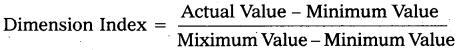
For the components of the HDI, individual indices are calculated according to the following formula.
Then, the HDI is calculated as a simple average of the three dimension indices. HDI value ranges from zsero to one. Countries with HDI below 0.5 are considered to have a low level of human development, those between 0.5 to 0.8 a medium level and those above 0.8 a high level. But as per Human Development Report 2014 (HDI, 2013) Countries have been grouped under four categories, (i) Countries in the HDI 0.8 and above are in the very high Human development group, (ii) Countries in HDI range 0.7 to 0.8 are in the High Human Development group, (iii) Countries in the HDI range 0.5 to 0.7 are in the range of Medium Human development group and (iv) Countries in the HDI range less than 0.5 are in the low. Human Development group. India’s HDI value is shown in the following table :
| Year | HDI Value |
| 1990 | 0.427 |
| 1995 | 0.546 |
| 2001 | 0.472 |
| 2002 | 0.592 |
| 2007 | 0.612 |
| 2010 | 0,519 |
| 2013 | 0.586 |
| 2017 | 0.640 |
| 2018 | 0.647 |
Very Short Answer Questions
Question 1.
Economic growth.
Answer:
Increase in the real output of goods and services over a long period of time is known as economic growth. It is a narrow concept. It explains quantitative changes. It relates to developed countries.
Question 2.
Economic Development.
Answer:
The Institutional changes and Tecyhnological changes which are used to achieve some amount of goods and services is known as economic development. It is a wider concept. It relates to developing countries.
Question 3.
Self Reliance.
Answer:
Self reliance implies that a country generates sufficient surplus to buy what it needs. It does not depend upon other countries for the resources of funds needed to acquire them. Self reliance allows imports.
Question 4.
Sustainable development.
Answer:
This concept was given by Brutland commission in the year 1987. It means to meet the needs of present generations, without comprising the ability of future generations.
Question 5.
Inclusive growth.
Answer:
Inclusive growth refers to both the pace and the pattern of the economic growth. This concept stresses the inclusiveness of the higher to scheduled population in the growth process, which is respected to bring in several other benefits as well to the economy. If the bottom 20% share can increase to 5 to 10% at lease, then it can be termed as inclusive growth.
Question 6.
Physical quality of Life Index (PQLI).
Answer:
If refers to physuical quality of life index. This concept can be studied with 3 ideas.
- Life expectancy – 65%
- Literacy Rate -.74%
- Infant molality rate 61/1000 live birth
This is a non income indicator of Economic development.
Question 7.
Human development Index (HDI).
Answer:
It refers to Human Development index. This concept measures the average achievement in three basic dimensions of human development. They are life expectancy at birth, adult literacy contained enrolment ratio and real GDP percapita based on purchasing power purity (PPP),
Question 8.
Gender related Development Index.
Answer:
This concept was introduced by Human development report (HDR) 1995. This concept is a composite index which measures the average achievement of population in the same dimensions as the HDI while adjusting for gender inequalities in the level of achievement in the three basic aspects of human development. It uses same variables as the HDI while adjusting for gender inequalities in the level of achievement in the three basic aspects of human development. It uses same variables as the HDI, dis eggregated by gender.
Question 9.
Social Progress Index (SPI).
Answer:
SPI is published by the non-profit social progress imperalised and it is based on the workings of Amartya Sen. This concept measures the well being of a society by observing social and environmental outcomes directly rather than the economic factors. The social and environmental factors include wellness, equality, inclusion, sustainability and personal freedom and safety.
Question 10.
Multi dimensional poverty Index (MPI).
Answer:
This concept was first introduced in the year 2010. It is an attempt designed to illustrate the many deprivations faced by the most several disadvantages. This concept requires a household to be deprived in multiple indicators at the same time. A person is multi dimensionally poor if the weighed indicators in which he or she is seprives add up to at least 33 percent.
Question 11.
Natural resources.
Answer:
Natural resources refers to land are and quality of soil forest wealth, good river system, minerals and Oil resources and ecosystem are included. For economic growth the existence of natural resources in abudance is essential.
Question 12.
Human Capital.
Answer:
Investment on human is called human capital most of the developing countries the people are illiterate. Their standard of living and mobility of labour is very low. The attitude and values of people do not encourage economic change and growth.
Question 13.
Vicious circles of poverty.
Answer:
A country is poor language it is poor. This concept was given by Ragnar Nurksc. The basic vicious circle stems from the fact that in developing countries total productivity is low and to deficiency of capital, market imperfections, economic backwardness and under development.
The vicious circle operates both on demand side and supply side. The demand side is that the low level of real income leads to a low level of demand the supply side, is that the low productivity reflected in low real income.
Question 14.
Capital formation.
Answer:
It refers to the net addition of capital stock such as equipment, buildings and other intermediate goods. A nation uses capital stock in combination of labour to provide services and to produce goods. An increase in this capital stock is known as capital formation.
Question 15.
Markatable surplus of agriculture.
Answer:
In refers to the success of agricultural output over and above what is required for subsistence living of the rural population. In case a country fails to produce a sufficient markable surplus it will be left with no choice select to import food grains which may cause a balance at payments problem.
Question 16.
Social factors.
Answer:
Social attitudes, values, and institutions also influence economic growth. These are rationality in throughout and action through on deliberate cultivation of scientific attitude and application of modem technology in order to increase productivity, raise levels of living and brings about social and economic equalisation, changes in attitudes due to modernisation of values lead to development of agriculture, industry and tertiary sectors of the economy.