Telangana TSBIE TS Inter 2nd Year Physics Study Material 15th Lesson Semiconductor Electronics: Material, Devices and Simple Circuits Textbook Questions and Answers.
TS Inter 2nd Year Physics Study Material 15th Lesson Semiconductor Electronics: Material, Devices and Simple Circuits
Very Short Answer Type Questions
Question 1.
What is an n-type semiconductor? What are the majority and minority charge carriers in it?
Answer:
When intrinsic Germanium / Silicon crystal is doped with a pentavalent impurity then “n-type semiconductor” will be formed.
The majority charge carriers are electrons and minority charge carriers are holes.
Question 2.
What are intrinsic and extrinsic semiconductors? [AP May ’18, Mar, ’15; June ’15]
Answer:
Intrinsic semiconductor :
Ultra high pure semiconductor are called “intrinsic semi-conductor”.
Extrinsic semiconductor :
The doped semi-conductor is called extrinsic semiconductor.
Question 3.
What is a p-type semiconductor? What are the majority and minority charge carriers in it? [TS May ’18, Mar. ’17; AP Mar. ’17]
Answer:
When third group impurities like boron, aluminium, galium, indium etc., are added to intrinsic semiconductor then it is called “p-type semiconductor.”
In p-type semiconductor majority, charge carriers are holes and minority charge carriers are electrons.
Question 4.
Give examples of “photosensitive substances”. Why are they called so? [AP May ’16]
Answer:
- Metals like zinc, cadmium and magnesium will respond to ultraviolet rays.
- Alkalimetals such as sodium, potassium, caesium and rubidium will respond to visible light.
These substances are called photo sensitive surfaces because they will emit electrons when light falls on them.
Question 5.
What is p-n junction diode? Define depletion layer. [TS Mar. ’19 May ’16]
Answer:
p-n semiconductor diode :
When a semiconductor material such as silicon or germanium crystal is doped in such a way that one side of it becomes a p-type and the other side becomes n-type then a p-n semi-conductor diode is formed.
Depletion layer :
The formation of a narrow region on either side of the junction which becomes free from mobile charge carriers is called “depletion layer”.
![]()
Question 6.
How is a battery connected to a Junction diode in i) forward and ii) reverse bias?
Answer:
In Forward Bias :
In a p-n junction diode if p-side is connected to positive terminal of a battery and n – side to negative terminal it is called “forward biased”.
In Reverse Bias :
If p-side is connected to negative terminal of the battery and n-side to positive terminal of the cell it is called “reverse biased”.
Question 7.
What is die maximum percentage of rectification in half wave and full wave rectifiers?
Answer:
The maximum percentage of rectification in a half wave rectifier is 40.6% and in a full wave rectifier maximum percentage of rectification is 81.2%.
Question 8.
What is zener voltage (VZ) and how will a zener diode be connected in circuits generally?
Answer:
When a zener diode is reverse biased at a particular voltage the current increases suddenly. The voltage at which the current increases is called “breakdown voltage” or “zener voltage”, so zener is always connected in “reverse bias”.
Question 9.
Write the expressions for the efficiency of a half wave rectifier and a full wave rectifier.
Answer:
Efficiency of half wave rectifier
![]()
Efficiency of full wave rectifier
![]()
Question 10.
What happens to the width of the depletion layer in a p – n junction diode when it is i) forward biased and ii) reverse biased? [AP Mar. ’19]
Answe:
When a p – n diode is forward biased thickness of depletion layer decreases and in reverse bias condition the thickness of depletion layer increases.
Question 11.
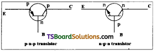
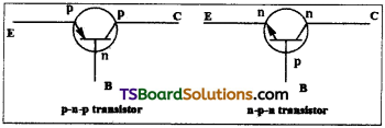
Draw the circuit symbols for p – n – p and n – p – n transistors. [TS & AP Mar. ’18, May ’17; AP May ’16, ’14; Mar. ’14; TS Mar. ’16]
Answer:
Question 12.
Draw the symbol of NOT gate and explain its operation. Give its truth table. [TS June ’15]
Answer:
NOT gate :
It has one input terminal and one output terminal. The output of NOT gate is the opposite of input i.e., if input is ‘0’ then output is ‘1’. If input is ‘1’ then output is ‘O’.

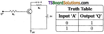
Implementation of NOT gate using a transistor :
NOT gate can be implemented with transistor. If A = 0 the emitter base junction is open and there is no current through the transistor. The current through the resistor. RL = 0 and Q becomes equal to a potential of 5V i.e., Q when A = 1 then Q = 1 in the emitter base junction. So large current flows and Q approximately 0 volt i.e., Q =0. Thus output is same as that of a NOT gate.
Truth tables of NOT gate :
The truth tables of NOT gate interms of low and high (0 and 1) are as given below.
Question 13.
Define amplifier and amplification factor.
Answer:
Amplifier :
Raising the strength of a weak signal is known as amplification and the device used for this purpose is called amplifier.
Amplification factor :
It is the ratio between output voltage to the input,
Voltage, (A) = \(\frac{V_0}{V_i}\)
![]()
Question 14.
In which bias, can a zener diode be used as voltage regulator? [AP Mar. 16; TS June 15]
Answer:
In reverse bias, zener diode can be used as voltage regulator.
Question 15.
Which gates are called universal gates? [TS Mar. ’15]
Answer:
NAND and NOR gates are known as the basic building blocks of logic gates or universal gates.
Question 16.
Write the truth tables of NAND gate. How does it differ from AND gate?
Answer:
| Truth Table | ||
| Input | Output | |
| A | B | Q |
| 0 | 0 | 1 |
| 1 | 0 | 1 |
| 0 | 1 | 1 |
| 1 | 1 | 1 |
The output of NAND gate is opposite to output of AND gate.
Short Answer Questions
Question 1.
What are n-type and p-type semiconductors? How is a semiconductor junction formed?
Answer:
n-type semiconductors :
When pentavalent impurities such as phosphorous (P), arsenic (As), antimony (Sb) are added to intrinsic semiconductors then they are called n-type semiconductors.
p-type semiconductors :
When trivalent. impurities such as Boron (B), Aluminium (AI), Galium (Ga), Indium (In) etc. are added to intrinsic semiconductor then it is called p-type semiconductor.
p-n junction :
A p-n junction is formed by adding a small quantity of pentayalent impurities in a highly controlled manner to a p-type silicon/germanium wafer.
- During the formation of p-n junction diffusion and drift of charge carriers takes place.
- In a p-n junction concentration of holes is high at p – side and concentration of electrons is high at n-side.
Due to the concentration gradient between p-type and n-type region holes diffuse to n- region and electrons diffuse to p-region.
Due to diffusion of changes a chargeless region is formed near junction called depleted layer.
Question 2.
Discuss the behaviour of p-n junction. How does a potential barrier develop at the junction?
Answer:
p-n junction :
A p-n junction is formed by adding a small quantity of pentavalent impurities in a highly controlled manner to a p-type silicon/germanium wafer.
- During the formation of p-n junction diffusion and drift of charge carriers takes place.
- In a p-n junction concentration of holes is high at p – side and concentration of electrons is high at n-side.
Due to the concentration gradient between p-type and n-type region holes diffuse to n- region and electrons diffuse to p-reglon. This leads to diffusion current.
Due to diffusion of electron an ionised donor is developed at n-region and due to diffusion of holes to n- region an ionised acceptor. These ions are immobile. So some – ve charge is developed in p – region and positive charge is developed in n-region. This space charge prevents further motion of electrons and holes near junction.
Depletion layer :
Both the negative and positive space charge regions near junc-tion are called depletion region.
![]()
Question 3.
Draw and explain the current-voltage (I-V) characteristic curves of a junction diode in forward and reverse bias.
Answer:
When a graph is plotted between junction potential ‘V’ and junction current T of a p-n junction then it is called V-I characteristics.
In forward bias p-side of p-n junction is connected to + ve terminal and n – side is connected to – ve terminal of external voltage ‘V’. The external voltage ‘V’ is gradually increased and junction current T is measured.
Initially junction potential is slowly increased in steps of 0.1 V. Until junction potential reaches a minimum value called threshold potential junction current is almost zero. ;
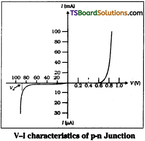
Once applied potential crosses threshold potential then junction current increases exponentially with applied voltage. On the reverse bias side nearly a steady current of few micro amperes was observed with applied voltage. When reverse bias potential reaches a high valued suddenly the diode is thrown into conduction. This is called breakdown potential.
Question 4.
Describe how a semiconductor diode is used as a half wave rectifier. [TS May. 18. Mar. 16; AP Mar. 16, 14]
Answer:
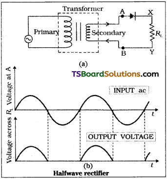
A junction diode allows current through it in forward bias only. In a half wave rectifier an a.c. source, p-n junction and load resistance (RL) are connected in series as shown.
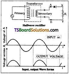
For ‘+ve’ half cycle p-n junction is for-ward biased so current flows through diode and we will get output current across load resistance.
For ‘+’ ve half cycle the p-n junction is reverse biased so current does not flow through p-n junction. So we are not able to get current through load resistance.
In half wave rectifier the out put voltage changes sinusoidally. But still it is flowing in only one direction through load resistance (RL) so input a.c. voltage is rectified.
Question 5.
What is rectification? Explain the work¬ing of a full wave rectifier. [AP Mar. ’18, ’15; May ’17, ’14; TS Mar. ’19. ’15, May ’17]
Answer:
Rectification :
The process of converting alternating current (a.c) into direct current (d.c) is called rectification. Instruments used for rectification is called rectifier.
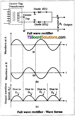
In a full wave rectifier, two p-n diodes are connected at the output side of a center-tapped transformer through a load resistance as shown.
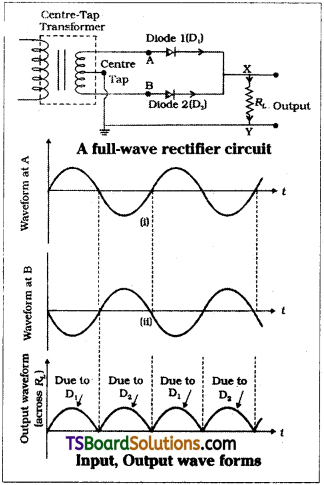
The centre tap will divide the output a.c. wave exactly into two equal halves say + ve half cycle and – ve half cycle.
Let diode D1 is connected to ‘+ve’ half cycle then it is forward biased. So current flows through D1 at the same time ‘-ve’ half cycle is applied to diode D2 so it is reverse biased and current does not flow through it. Hence we will get output through diode D1.
As the applied a.c. wave is progressing we will get ‘+ve’ half cycle to diode D2 at that time diode D2 is forward biased so current flows through D2. But now ‘-ve’ half cycle is applied to diode D1. So it is in reverse bias hence current does not flow through D1.
In full wave rectifier diodes D1 and D2 will conduct current alternately. Even though out put current oscillates between a minimum and maximum value it always passes through same direction through load resistance (RL). So input a.c. is rectified.
![]()
Question 6.
Distinguish between half-wave and full-wave rectifiers. [AP Mar. ’19. ’17; May. ’16; TS Mar. ’18, May, ’18]
Answer:
| Half wave rectifier | Full wave rectifier |
| i) In half wave rectifier only one diode is used. | i) In full wave rectifier two diodes are used. |
| ii) Every positive half cycle is rectified. | ii) Both positive and negative half cycles are rectified. |
| iii) Electric current is not continuous. | iii) Electrical current is continuous. |
| iv) In the negative half cycle of a.c. rectification will not take place. | iv) In the negative half cycle of a.c. also rectification will take place. |
| v) Efficiency is less. | v) Efficiency is high. |
| vi) Ripple is less. | vi) Ripple is high. |
Question 7.
Distinguish between zener breakdown and avalanche breakdown.
Answer:
Avalanche breakdown:
- In avalanche breakdown, the thermally generated electrons and holes acquire sufficient energy from the applied potential to produce new carries by removing valence electrons from their bonds.
- These new carries, in turn produce additional carriers again through the process of disrupting bonds.
- This cumulative process is referred to as avalanche multiplication. It results in the large flow of current, and the diode finds itself in avalanche breakdown.
- This occurs in lightly doped diodes at high reverse bias voltages.
Zener breakdown:
- If a diode is heavily doped, direct rupture of covalent bonds takes place because of strong electric field at the junction.
- As a result of heavy doping of p and n regions, the depletion region width becomes very small and an applied voltage causes an electric field of 107 V/m of the junction making condition suitable for zener breakdown. This occurs in heavily doped diodes at low reverse bias voltages.
Question 8.
Explain hole conduction in intrinsic semiconductors.
Answer:
Intrinsic semiconductors :
Semiconductors with ultra high pure state are called “intrinsic semiconductors”.
In pure germanium (Ge) or silicon(Si) crystal every germanium or Silicon atom forms four covalent bonds with neighbouring Ge/Si crystal.
At very low temperatures intrinsic semiconductors are insulators. When temperature increases electrons absorbs more thermal energy and it may become a free electron and that atom will become positive.
In intrinsic semiconductors number of free electrons (ne) is equal to number of holes (nh)
Due to thermal energy some of the electrons escapes from the bonds and an empty spaces left behind in the valence band. This vacancy in the valence band is called a “hole”.
Due to applied electric field the holes drift in opposite direction to the electrons with lesser speed and behave like positive charge carriers and current is produced due to the both electrons and holes.
Current contribution by electrons (le) and holes (Ih) is same.
∴ In an intrinsic semiconductor ne = nh = ni.
Total current I = Ie + Ih
Question 9.
What is a photodiode? Explain its working with a circuit diagram and draw its I-V characteristics.
Answer:
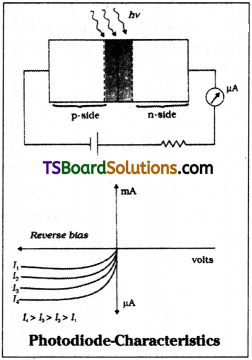
Photodiode :
A photodiode consists of a p-n junction diode with a transparent window to allow light to fall on to the junction.
When light photons falls on this p-n junction it will produce electron – hole pair. These pairs are separated by the applied potential ‘V’ before they recombine. The magnitude of photo current depends on intensity of incident light.
i.e., current, i ∝ intensity of light I. So a photodiode can convert light intensity variations into current variations. This property is used to detect optical signals.
The I-V characteristics of photodiode can easily studied with reverse bias potential on it. The junction voltage ‘V’ and current ‘I’ characteristics are as shown in figure.
Question 10.
Explain the working of LED and what are its advantages over conventional incandescent low power lamps.
Answer:
Light emitting diode (LED) :
It is a highly doped p-n junction. Under forward biased condition it emits spontaneous radiation in visible region. This p-n junction is coated with a transparent cover so that emitted light can come out.
Working :
When LED is forward biased holes are driven to n-region and electrons are driven to p-region due to electric potential of battery. As a result charge concentration near junction region increases. The electrons and holes while recombining with them they will release the recombination energy in the form of light photons.
Generally LED breakdown voltages are very low such as 5V. For the fabrication of visible LED the energy band gap of 1.8 eV to 3 eV is necessary. The minimum energy gap must be 1.8 eV. It LED materials are selected with in this range then we can get visible light in the wavelength range of 0.7 pm to 0.4 pm or in wavelength range of 7000Å to 4000Å.
Generally LEDs are biased to emit light with maximum efficiency. Intensity of light emitted depends on strength of current. Colour of light depends on energy band width.
For gallium arsenide-phosphide energy gap is ≅ 1.9 eV, it will emit red light.
For galium Arsenide Ga, As energy gap is ≅ 1.4 eV, it will emit infrared light. These LEDs are widely used in T.V remote control and in burglar alarm systems.
Advantages of LED:
- They require low operational voltage and consumes less power.
- They are surged and life period is very high.
- They will respond very quickly to current changes.
![]()
Question 11.
Explain the working of a solar cell and draw its I-V characteristics.
Answer:
Solar cells :
A solar cell is also a p-n junction which generates emf when solar radiation falls on it. A p-type silicon wafer of nearly 300 pm is taken. A n-type impurity layer of nearly 0.3 µm is developed on it through diffusion process, junction surface area Is kept large. A metallic grid is deposited on n-region and the other p- side is also coated with metal. These two will provide electrical contact.
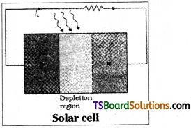
Working :
Generally semiconductors width a band width of nearly 1.5 eV or less are selected in solar cells when solar radiation falls on p-n junction electron hole pair is produced.
Separation of electrons and holes will takes place (before they recombine) due to the electric field produced across depleted region.
Electrons on reaching n – side are collected by front metallic grill. Holes reaching p – side are collected by back contact.
V.I characteristics of solar cells are drawn in fourth quadrant of the coordinate axis. It is as shown in figure.
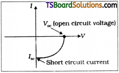
Solar cells are widely used to tame solar energy from which electricity is produced.
These solar cell plays an important role in supplying electrical energy to satellites and in remote forest areas.
Question 12.
Explain the different transistor configurations with diagrams.
Answer:
Transistors are connected in three ways. They are :
- Common base configuration
Common emitter configuration - Common collector configuration
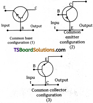
1) Common base configuration :
In this configuration, base is common to both input and output. Base terminal is earthed and input is given across base emitter and output is taken across base collector.
2) Common emitter configuration :
In this configuration emitter is common to both input and output. The emitter is earthed and input is given across base emitter and output is taken across collector emitter.
3) Common collector configuration :
In this configuration, collector is common to both input and output. The collector is earthed and input is given across base collector and output is taken across emitter-collector.
Question 13.
Explain how transistor can be used as a switch?
Answer:
In a transistor D.C. input voltage Vi = IBRB + VBE …….. (1)
Sum of D.C potential between emitter base i.e., and product of base current and base resistance (VBE) / IBRB.
D.C. output voltage V0 = VCC – ICRC ……….. (2)
As far as Vi is less than active region minimum voltage of 0.6 V (nearly), output voltage V0 is high because Collector current (IC) is zero.
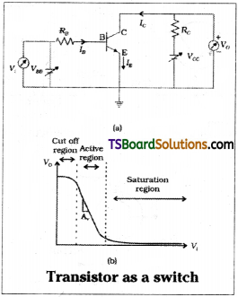
When input voltage Vi increases collector current IC increases and output voltage V0 decreases because V0 = Vi – ICRC. i.e., when Vi is less V0 is high and whenVi is high output voltage V0 is less. By changing the input potential a transistor can be made to move between high and low states or ON and OFF states. Hence by selecting proper input voltage Vi a transistor can be used as a switch.
Question 14.
Explain how transistor can be used as an oscillator.
Answer:
In an oscillator, we will get out put without any external input. The oscillator circuit is as shown in figure.
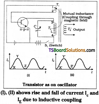
When switch ‘S1‘ is closed a surge current will flow in transistor and it produces output in collector circuit. Current in coil T2 will gradually increase from minimum value ‘x’ to maximum value ‘y’ with changing time. Current in T2 is connected to oscillator LC in collector circuit. This induces current in coil T1 due to inductive coupling between T1 and T2. Coil T1 is connected to emitter base circuit. So a part of output is given as feedback to input.
When collector current reaches maximum value rate of change in collector current is zero. So induced current in T1 is zero i.e., input feedback is zero. So collector current begin to decrease while decreasing again emf is induced in T1 and feedback is given to emitter base circuit. Like this the signal is self sustained
Frequency of oscillator υ = \(\frac{1}{2 \pi \sqrt{\mathrm{LC}}}\)
In this way a transistor can be used as an oscillator.
![]()
Question 15.
Define NAND and NOR gates. Give their truth tables. [TS Mar. ’17; AP June ’15]
Answer:
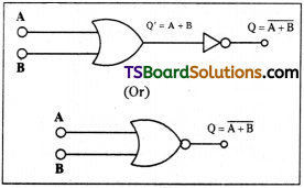
NOR Gate :
It is the combination of OR gate and NOT gate OR + NOT = NOR.
In this logic gate the output of OR gate is given to the input of NOT gate as shown in figure.
| Truth Table | ||
| Input | Output | |
| A | B | Q |
| 0 | 0 | 1 |
| 1 | 0 | 0 |
| 0 | 1 | 0 |
| 1 | 1 | 0 |
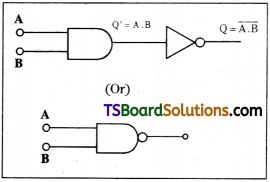
NAND gate :
It is the combination of AND gate and NOT gate.
AND + NOT = NAND.
In this logic gate the output of AND gate is given to the input of NOT gate.
| Truth Table | ||
| Input | Output | |
| A | B | Q |
| 0 | 0 | 1 |
| 1 | 0 | 1 |
| 0 | 1 | 1 |
| 1 | 1 | 0 |
The NAND and NOR gates are basic build¬ing blocks of logic gates; because any logic gates can be constructed by using only NAND or only NOR gates.
Question 16.
Explain the operation of a NOT gate and give its truth table. [TS June ’15]
Answer:
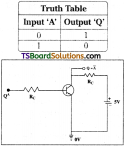
NOT gate :
It has one input terminal and one output terminal. When the input is low, the output is high and when the input is high, the output is low.
Implementation of NOT gate using a transistor :
NOT gate can be implemented with transistor. If A = 0 the emitter base junction is open and there is no current through the transistor. The current through the resistor. RL = 0 and Q becomes equal to a potential of 5V i.e., Q when A = 1 then Q = 1 in the emitter base junction. So large current flows and Q approximately 0 volt i.e., Q =0. Thus output is same as that of a NOT gate.
Truth tables of NOT gate :
The truth tables of NOT gate interms of low and high (0 and 1) are as given below.
Long Answer Questions
Question 1.
What is a junction diode? Explain the for-mation of depletion region at the junction. Explain the variation of depletion region in forward and reverse biased condition.
Answer:
p-n junction :
A p-n junction is formed by adding a small quantity of pentavalent impurities in a highly controlled manner to a p-type silicon/germanium wafer.
During the formation of p-n junction diffusion and drift of charge, carriers takes place.
In a p-n junction concentration of holes is high at p – side and concentration of electrons is high at n-side. Due to the concentration gradient between p-type and n-type regions holes diffuse to n-region and electrons diffuse to p-region. This leads to diffusion current.
Due to diffusion of electron an ionised donor is developed at n-region and due to diffusion of holes to n- region an ionised acceptor. These ions are immobile. So some – ve charge is developed in p – region and positive charge is developed in n-region. This space charge prevents further motion of electrons and holes near junction.
Depletion layer :
Both the negative and positive space charge regions near junction are called depletion region.
Variation of depletion region :
In forward bias due to applied voltage electrons from n – region crosses junction layer and goes to p-region. Similarly holes from p-region crosses junction and goes to n-region. Since charge carriers are freely crossing the junction depleted region vanishes in forward bias condition.
In reverse bias condition electrons in n- region are attracted by + ve terminal of bat-tery connected to it. Similarly holes in p – region are attracted by ’-ve’ terminal con-nected to it. As a result charges will travel towards battery terminals. We can not find charge carriers near p-n junction.
So in reverse bias condition width of depleted region increases.
![]()
Question 2.
What is a rectifier? Explain the working of half wave and full wave rectifiers with diagrams.
Answer:
The process of converting alternating current (a.c) into direct current (d.c) is called “rectification”. Instruments used for rectification is called “rectifier”.
A junction diode allows current through it in forward bias only. In a half wave rectifier an a.c. source, p-n junction and load resistance (RL) are connected in series as shown.
For ‘+ve’ half cycle p-n junction is forward biased so current flows through diode and we will get output current across load resistance.
For + ve half cycle the p-n junction is reverse biased so current does not flow through p-n junction. So we are not able to get current through load resistance.
In half wave rectifier the out put voltage changes sinusoidally. But still it is flowing in only one direction so input a.c. voltage rectified.
In a full wave rectifier two p-n diodes are connected at the output side of a center tapped transformer through a load resistance as shown.
The centre tap will divide the output a.c. wave exactly into two equal halves say + ve half cycle and – ve half cycle.
Let diode D1 is connencted to ’+ve’ half cycle then it is forward biased. So current flows through D1 at the same time ‘-ve’ half cycle is applied to diode D2. So it is reverse biased and current does not flow through it. Hence we will get output through diode D1.
As the applied a.c. wave is progressing we will get ‘+ve’ half cycle to diode D2 at that time diode D2 is forward biased so current flows through D2. But now -ve’ half cycle is applied to diode D1. So it is in reverse bias hence current does not flow through D1.
In full wave rectifier diodes D1 and D2 will conduct current alternately. Even though out put current oscillates between a minimum and maximum value it always passes through same direction. So input a.c. is rectified.
Question 3.
What is a zener diode? Explain how it is used as a voltage regulator.
Answer:
Zener diode :
A zener diode is a highly doped p-n junction with sharp breakdown voltage. Generally zener is operated in “reverse bias condition”.
Note:
In forward bias condition zener diode will also act as ordinary p-n junction.
Zener diode as voltage regulator :
Principle :
Zener diode has sharp breakdown voltage in “reverse bias condition”.
In zener diode release of large scale of charge carriers at breakdown voltage is due to field emission of electrons from host atoms. For field ionisation nearly an electric field of 106 V/m is necessary.
The speciality of zener diode is even though current through zener increases largely its potential (zener potential) remains almost constant.
Working :
Let a zener diode is connected to unregulated supply through a series resistance Rs. The value of zener voltage is selected such that zener voltage Vz is less than the minimum value of unregulated supply. A load resistance RL is connected parallel to zener. Output is taken across load resistance RL.
Case – I :
Let voltage of unregulated supply is at Its minimum value say Vi min. Zener potential Vz is constant. So Vi min – Vz is voltage drop across Rs. Current through Rs = Imin
= \(\frac{V_{i min}-V_z}{R_s}\)
Load current, IL = \(\frac{V_z}{R_L}\)
∴ Current through zener Iz min = Imin – \(\frac{V_z}{R_L}\)
Case – II :
When applied voltage is maximum say, Vi max then voltage drop across
Rs = Vi max – Vz
Maximum current through Rs is
Imax = \(\frac{V_{i max}-V_z}{R_s}\)
Current through zener is also max.
Iz max = Imax = \(\frac{V_z}{R_L}\)
In zener diode voltage regulator voltage changes in unregulated supply are converted into current changes in series resistance Rs. These current changes are absorbed by zener.
As a result we will get a constant voltage and current at output. In this way zener diode acts as a voltage regulator.
Question 4.
Describe a transistor and explain its working.
Answer:
Transistor :
A transistor is a three layered electronic device. These layers are called emitter, base and collector.
Transistors are two types 1) p-n-p 2) n-p-n.
Emitter :
Emitter region is of moderate size. It is heavily doped. It supplies large number of majority charge carriers for the current flow through transistor.
Base :
Width of base region is very less. It is lightly doped nearly with 3 to 5% Impurity concentration of emitter.
Collector :
Size of collector region is larger than emitter. It is moderately doped (i.e., impurity concentration is less than emitter).
Biasing of transistor :
In a transistor for transistor action to takes place (i) Emitter base region must be forward biased, (ii) Base collector region must be reverse biased, (iii) Forward bias emitter base potential VEB must be less than reverse bias collector base potential VCB.
If a transistor is biased as above, then the transistor is said to be in active state.
Working principle :
Electrons/holes in emitter region are injected into base region due to forward bias potential in emitter base region.
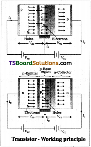
In base region nearly 3 to 5% of electrons/ holes are recombined so a small amount of current (IB) will flow in emitter base circuit. Due to less impurity concentration the remaining charges injected into base will cross base collector region.
The high reverse bias potential in base collector region will act as forward bias for the charges left unrecombined in base region.
So these charges are attracted by collector region. These charges will recombine at collector region and some current (IC) will flow in base collector region.
In a transistor emitter current (IE) = Base current (IB) + Collector current (IC)
∴ IE = IB + IC
Hence transistor is a current controlled device.
![]()
Question 5.
What is amplification? Explain the working of a common emitter amplifier with necessary diagram.
Answer:
Amplifier :
An amplifier is an electronic device used to strengthen weak signals.
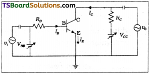
Transistor as an amplifier (C.E. configuration) :
A transistor can be used as an amplifier in its active region. In this region output voltage V0 increases drastically even for a small change in input voltage’ Vi‘.
In transistor amplifier the mid point of active region is taken as operating point (also called input potential) on which varying signal voltage is superposed. This variation is magnified at output side by a factor equals to amplification factor p.
In a transistor output voltage of collector, VOC = VCE + ILRL
Input voltage VBB = VBE + IBRB when input signal voltage Vi ≠ 0 the,
VBE + Vi + VBE + IBRB + ∆IB(RB + ri)
Where ri is input resistance.
Input signal voltage
Vi = ∆IB(RB + ri) = r∆IB.
Current amplification factor β is defined as the ratio of change in collector current ∆IC to change In base current ∆IB when VCC Is constant.
![]()
Voltage amplification factor Av :
It is defined as the ratio of output signal voltage (V0) to input signal voltage (Vi).
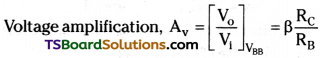
Question 6.
Draw an OR gate using two diodes and explain its operation. Write the truth table and logic symbol of OR gate.
Answer:
Implementation of OR gate using diodes :
Let ‘D1‘ and ‘D2‘ represent two diodes. A potential of 5V represent the logical value 1 and a potential of 0V represents the logical value zero.
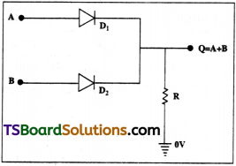
When A = 0, B = 0 both the diodes are reverse biased and there is no current through the resistance. So, the potential at ‘Q’ is zero, i.e., Q = 0. When A = 0 or B = 0 and the other equal to a potential behaves like a closed switch. The output potential then becomes 5V. i.e., Q=l. When both A and B are 1, both the diodes are forward biased and the potential at Q’ is same as that at A and B which is 5V i.e., Q =1. The output is same as that of the OR gate.
Truth table of OR gate :
The truth table of OR gate interms of low, high; 0 and 1 are below.
| Truth Table | ||
| Input | Output | |
| A | B | Q |
| 0 | 0 | 0 |
| 1 | 0 | 1 |
| 0 | 1 | 1 |
| 1 | 1 | 1 |
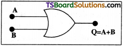
Logical symbol of OR gate :
The logical function OR is represented by the symbol plus. So that the output, Q = A + B
Questuion 7.
Sketch a basic AND circuit with two diodes and explain its operation. Explain how doping increases the conductivity in semiconductors?
Answer:
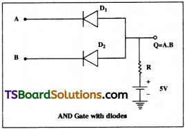
AND gate :
- It has two input terminals and one output terminal.
- When both the inputs low or one of the input is low the output is low in an AND gate.
- The output of the gate is high only when both the inputs are high.
- The output of the gate is high only when both the inputs are high.
- If the input of the gate are A and B and the outputs in Q than Q is logical function of A and B. The value of Q for different combinations of A and B is shown by means of a table called truth table.
Truth Table :
It is defined as the table that shows the values of the output of all possible combinations of the value of the input variables.
| Truth Table | ||
| Input | Output | |
| A | B | Q |
| 0 | 0 | 1 |
| 1 | 0 | 0 |
| 0 | 1 | 0 |
| 1 | 1 | 0 |
Implementation of AND gate using diodes:
- Let D1 and D2 represent two diodes. A potential of 5V represents the logical value 1 and potential of OV represents the logical value zero (0).
- When A = 0, B = 0, both the diodes D1 and D2 are forward biased and they behave like open switches. There is no current through the resistance R’ making the potential of Q equal to 5V i.e., Q = 1. The output is same as that of an AND gate.
Doping – Conductivity of semiconductors:
When a p – type impurity is doped it will develop acceptor energy levels near valance band in Forbidden region. So Forbidden gap width decreases and electrons can easily sent to conduction band.
When n-type impurities are doped they will develop donor energy levels near conduction band in Forbidden gap. As a result Forbidden gap decreases and electrons in valance band will be sent to conduction band with very little energy (< 0.01 eV).
As a result due to doping conductivity of semiconductors will increase.
Problems
Question 1.
In a half wave rectifier, a p-n junction diode with internal resistance 20 ohm is used. If the load resistance of 2 ohm is used in the circuit, then find the efficiency of this half wave rectifier.
Answer:
Internal resistance of diode rf = 20 Ω;
Load resistance RL = 2kΩ = 2000 Ω
Efficiency of half wave rectifier =
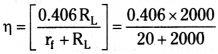
\(\frac{812}{2020}\) = 0.4019
% of η = 0.4019 × 100 = 40.19% = 40.2%
Question 2.
A full wave p-n junction diode rectifier uses a load resistance of 1300 ohm. The internal resistance of each diode is 9 ohm. Find the efficiency of this full wave rectifier.
Answer:
Load resistance RL = 1300 Ω;
Internal resistance of diode rf = 9 Ω
Efficiency of full wave rectifier
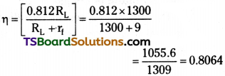
% of efficiency η = 0.8064 × 100 = 80.64%
Question 3.
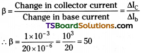
Calculate the current amplification factor b (beta) when change in collector current is 1 mA and change in base current is 20 mA.
Answer:
Change in collector current ∆IC = 1mA = 1 × 10⁻³ A
Change in base current ∆Ib =20µA = 20 × 10-6 A
Current amplification
![]()
Question 4.
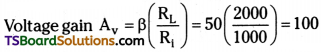
For a transistor amplifier, the collector load resistance RL = 2k ohm and the input resistance Ri = 1 k ohm. If the current gain is 50, calculate voltage gain of the amplifier.
Answer:
Load resistance RL = 2 kD = 2000 Ω;
Input resistance Rj = 1 kQ = 1000 Ω
Current gain b = 50 ; Voltage gain Av = ?