Here students can locate TS Inter 2nd Year Physics Notes 10th Lesson Alternating Current to prepare for their exam.
TS Inter 2nd Year Physics Notes 10th Lesson Alternating Current
→ Alternating Current (AC): If the supplied voltage varies like a sine function then it is called “alternating voltage” and the current driven in the circuit is called “alternating current”.
→ Preference of AC:
- We prefer AC supply to DC supply because it is easy to produce.
- It can be easily transformed from high voltage to low voltage or from low voltage to high voltage. 3) It is easy to transmit to longer distances with less line losses.
→ AC Voltage applied to a Resistor: When a AC Voltage V = Vm sin cot is applied to a pure resistor then current, I = \(\frac{V_m}{R}\) sin ωt = \(\frac{\mathrm{V}}{\mathrm{R}}\) and Im = \(\frac{V_m}{R}\)
In a pure resistor applied voltage and current through resistor are in phase, i.e., when voltage is maximum then current is also maximum. Similarly when voltage is minimum the current is also minimum.
→ Average power consumed in a resistor P = \(\frac{1}{2}\)Im2 R(or) P = I2R = VI (∵I = Im/√2)
![]()
→ AC Voltage through an Inductor: in a pure inductor (i.e., where resistance R = 0) applied voltage V = Vm sin ω0t.
Current through inductor I = Im sin (ωt – π/2) In a pure inductor current lags behind
voltage by a phase angle Φ = \(\frac{\pi}{2}\)
Reactance of Inductor XL = ωL
Im = \(\frac{V_m}{X_L}\)
→ AC Voltage through a pure Capacitor:
When AC voltage is applied to a pure capacitor its reactance Xc = \(\frac{1}{\omega \mathrm{C}}\). (called capacitive reactance)
Voltage across capacitor V = Vm sin ωt
Current in the capacitor I = Im sin (ωt + \(\frac{\pi}{2}\)) In a capacitor current (I) leads the applied voltage by an angle \(\frac{\pi}{2}\).
Power dissipation in a pure capacitor Pc = 0
→ Reactance: The resistance of active components like Inductance (L) and Capacitance (C) changes with frequency (co) of current supplied.
The resistance that changes with frequency is called reactance (X).
Reactance of Inductance = XL = ωL
Reactance of capacitance = XC = \(\frac{1}{\omega \mathrm{C}}\)
→ Impedance (Z): The total resistance of a circuit with reactive components like inductance or capacitance or both along with resistance ‘R’ is given by Z = R + XC + XL
The total resistance of a circuit with reactive components is called Impedance.
Impedence (Z) of R-L circuit Z = R + ωL
Impedance of C – R circuit Z = \(\sqrt{R^2+\left(\frac{1}{\omega C}\right)^2}\)
Impedance of L – C circuit Z = \(\sqrt{\left(\omega L-\frac{1}{\omega \mathrm{C}}\right)^2}\)
→ Phasor diagram: Phasor diagram represents the current in a circuit which contains resistance (R) and reactive components like inductance (L) and capacitance ‘C’.
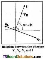
→ In a circuit let I is the phasor represents the current it is always parallel to VR i.e., vol¬tage along resistance.
Voltage across capacitor Vc lags behind I by an angle \(\frac{\pi}{2}\).
Voltage across inductor VR leads current phasor I by an angle \(\frac{\pi}{2}\)
Phasor relation is V = VR + VL + Vc
→ Impedance diagram: Graphical represen-tation impedance of Z = \(\sqrt{\mathrm{R}^2+\left(\mathrm{X}_{\mathrm{C}}-\mathrm{X}_{\mathrm{L}}\right)^2}\) in the form of a right angle triangle is called “impedance diagram”.
→ Impedance diagram
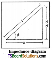
Where
X – direction represents Resistance R.
Y – direction represents total reactance (XC – XL) and Hypotenuse represents impedance.
![]()
→ Series LCR Circuit: In series LCR circuit an inductance (L), capacitance ‘C’ and resistance ‘R’ are connected to an AC source. AC voltage through LCR ciruit. Let a voltage V = Vm sin cot is applied to series LCR circuit.
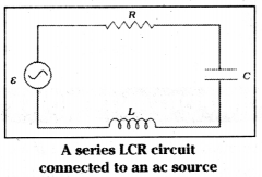
Total voltage in the circuit V = VL + VR + VC
Impedance of circuit,
Z = \(\sqrt{R^2+\left(X_C-X_L\right)^2}=\sqrt{R^2+\left(\omega L-\frac{1}{\omega C}\right)^2}\)
Maximum current Im = \(\frac{\mathrm{V}_{\mathrm{m}}}{\mathrm{Z}}\)
Phase angle Φ = tan\(\left(\frac{\mathrm{X}_{\mathrm{C}}-\mathrm{X}_{\mathrm{L}}}{\mathrm{R}}\right)\)
Resonating frequency, ω0 = \(\frac{1}{\sqrt{\mathrm{LC}}}\)
→ Resonance: Resonance is a physical phenomenon at which a system tends to oscillate freely. This particular frequency is called natural frequency. At resonance amplitude of oscillations is large.
→ Series LCR circuit-Resonant frequency:
Resonant frequency of series LCR circuit is ω0 = \(\frac{1}{\sqrt{\mathrm{LC}}}\)
→ Sharpness of resonance: In case of series LCR circuit resonant frequency ω0 = \(\frac{1}{\sqrt{\mathrm{LC}}}\)
However the amplitude of oscillation is high in between the frequencies ω2 = ω0 + Δω and ω1 = ω0 – Δω. Where Δω is a small frequency change from ω0?
ω2 – ω1 = 2Δω is called band width of resonance, ω0/2Δω is called sharpness of resonance.
Note: Tuning circuits with sharp resonance are considered as very good frequency selectors.
→ Power of AC circuit and Power factor:
Power of AC circuit P = I2Z cosΦ. It indicates that power depends not only on current I and Impedance Z of circuit but also cosine of phase angle between I and Z.
The term cos Φ is called power factor.
→ Wattless current: In a circuit with pure inductance or pure capacitance the phase angle between voltage and currents are Φ = \(\frac{\pi}{2}\), so cos Φ = 0. hence no power is dissipated through then even though current passes through them. This current is referred as wattless current.
→ Transformer: A transformer works on the principle of electromagnetic induction”. A transformer will convert high voltage AC current into low voltage AC current or Low voltage AC current into high voltage AC current by keeping VI = constant.
![]()
→ Turns ratio: The ratio of number of turns in primary coil (Np) to number of turns in secondary coil (Ns) is called “transformer turns ratio”.
Voltage at secondary, Vs = \(\)Vp and
Current at secondary, Is = \(\)Ip
Note:
- Transformers with Ns/ Np > 1 are called step up transformers.
- Transformers with Ns / Np < 1 are called step down transformers.
- A transformer will work for a.c currents only.
- The Equation Vs = \(\left(\frac{\mathrm{N}_{\mathrm{s}}}{\mathrm{N}_{\mathrm{p}}}\right)\)Vp is applicable for ideal transformers. But in real case a small amount of energy (less than 5%) is wasted due to
- Flux leakage
- Resistance of windings
- Eddy currents and
- Hysteresis.
→ In AC circuits: Voltage at any instant V = Vm sin cot current at any instant I = Im sin cot (where Im = \(\frac{V_m}{R}\))
→ Root mean square values (R.M.S Values):
R.M.S. value of current I = Im / √2 = 0.707 Im
R.M.S. value of voltage V = Vm /√2 = 0.707 Vm
Average power
P̅ = \(\frac{1}{2}\)Im2R = \(\frac{1}{2}\)Iv2/R = \(\frac{1}{2}\)ImVm
→ Relation between V and I: Vm = Im R and V
= I R and P = VI = I2R = \(\frac{\mathrm{V}^2}{\mathrm{R}}\).
→ In pure Inductors : V = Vm sin ωt ; I = Im (sin ωt – π/2)
In inductance current lags behind voltage by 90° or \(\frac{\pi}{2}\) radians.
Inductive reactance XL = ωL = 2πυL
Maximum current through inductor Im = \(\frac{\mathrm{V}_{\mathrm{m}}}{\mathrm{X}_{\mathrm{L}}}\)
→ In pure Capacitors : Voltage across capacitor V = \(\frac{q}{c}\) = Vm sin ωt.
Current in capacitor I = Im sin (ωt + π/2).
In a pure capacitor current I leads voltage V by a phase angle 90° or \(\frac{\pi}{2}\) radians.
Reactance of capacitor Xc = \(\frac{1}{\omega \mathrm{C}}\); Maximum current Im = \(\frac{V_m}{(1 / \omega c)}=\frac{V_m}{X_c}\)
Instantaneous power supplied Pc = \(\frac{\mathrm{i}_{\mathrm{m}} \cdot \mathrm{V}_{\mathrm{m}}}{2}\) sin 2ωt.
Power supplied to capacitor over one complete cycle is zero.
→ In a resistor: Applied Voltage V = Vm sin ωt
Current I = \(\frac{I_m}{R}=\frac{V_m}{R}\) sin ωt
Average power dissipated
P̅ = \(\frac{1}{2}\)I2mR = \(\frac{V^2}{R}\) = VI = \(\frac{\mathrm{V}_{\mathrm{m}} \mathrm{I}_{\mathrm{m}}}{2}\).
→ In series LCR circuit,
Total potential in circuit V = VL + VR + Vc.
= Vm/\(\frac{V_m}{Z}\)
Impedance of circuit Z = \(\sqrt{\mathrm{R}^2+\left(\mathrm{X}_{\mathrm{C}}-\mathrm{X}_{\mathrm{L}}\right)^2}\)
Phase difference Φ = tan-1\(\left[\frac{\mathrm{X}_{\mathrm{C}}-\mathrm{X}_{\mathrm{L}}}{\mathrm{R}}\right]\)
Resonant frequency ω0 = \(\frac{1}{\sqrt{\mathrm{LC}}}\)
At Resonance ωL = \(\frac{1}{\omega \mathrm{C}}\) and Impedance Z = R.
Band width of circuit 2Δω = ω2 – ω1
(where ω2 > ω1)
Sharpness of circuit Q = \(\frac{\omega_0}{2 \Delta \omega}=\frac{\omega_0 L}{R}\)
Power in AC circuit P = I2Zcos Φ = VIcos Φ
where is phase between voltage V and current I.
![]()
→ In LC CircuIt : Electrical energy stored In charged capacitor UE = \(\) where qm = Im/ω0
Resonant frequency ω0 = \(\frac{1}{\sqrt{\mathrm{LC}}}\)
In transformer;
Turns ratio = \(\frac{\mathrm{N}_{\mathrm{s}}}{\mathrm{N}_{\mathrm{p}}}\)
Secondary voltage Vs = \(\left[\frac{\mathrm{N}_{\mathrm{s}}}{\mathrm{N}_{\mathrm{p}}}\right]\)Vp
Secondary current Is = \(\left[\frac{\mathrm{N}_{\mathrm{p}}}{\mathrm{N}_{\mathrm{s}}}\right]\)Ip
Back emf in primary Vp = -Np \(\frac{\mathrm{d} \phi}{\mathrm{dt}}\)
Induced emf or voltage in secondary Vs = Ns \(\frac{\mathrm{d} \phi}{\mathrm{dt}}\)